9
I/O
Description:
It determines the analog outputs gain according to the equations of Table 9.3 on page 9-9.
P253 - AO1 Output Signal
P256 - AO2 Output Signal
Range: 0 = 0 to 10 V
1 = 0 to 20 mA
2 = 4 to 20 mA
3 = 10 V to 0
4 = 20 mA to 0
5 = 20 to 4 mA
Description:
These parameters configures if the analog outputs signal will be in current or voltage, with direct or reverse reference.
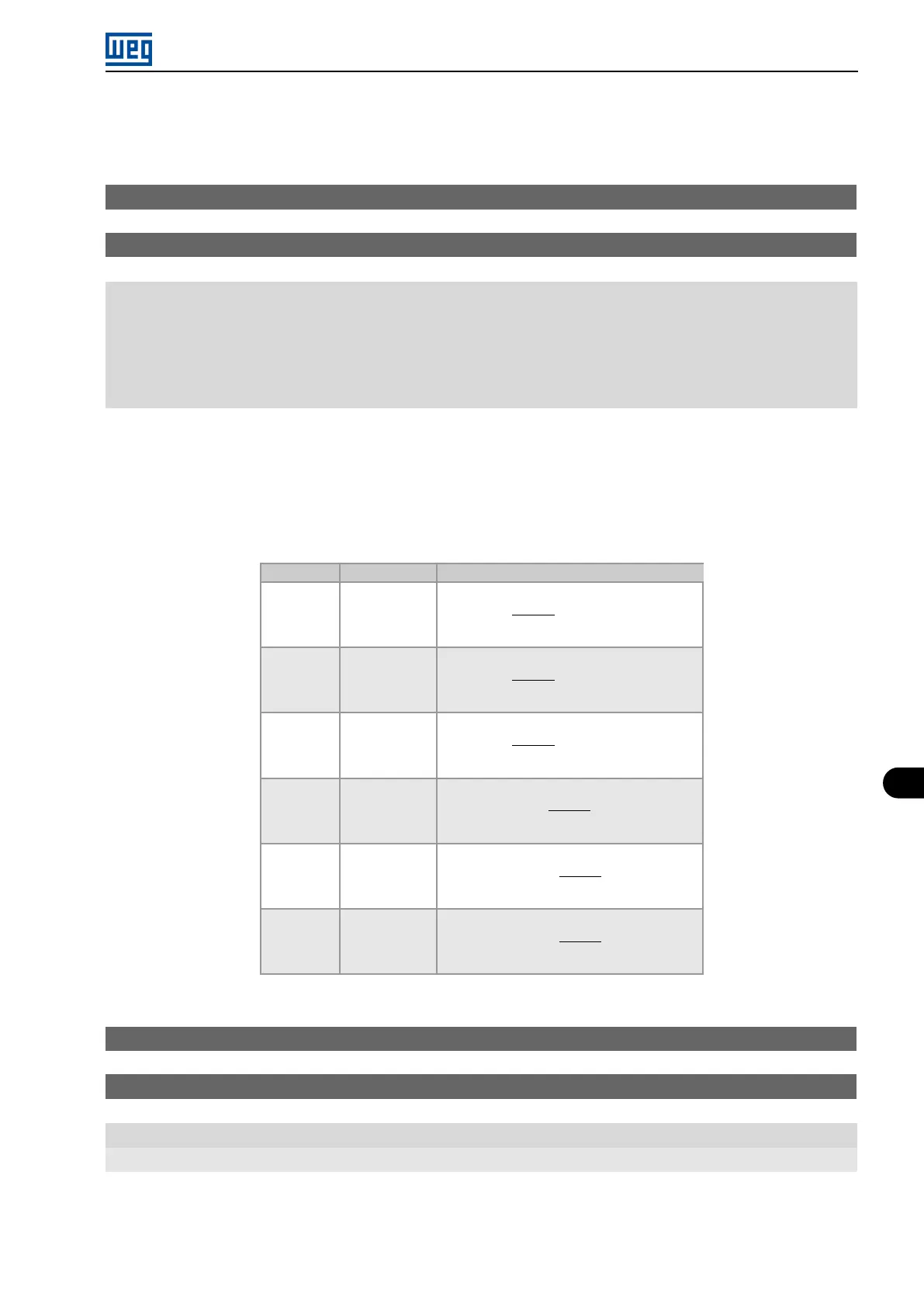
Table 9.3 on page 9-9 below summarizes the configuration and equation of the analog output, where the relationship
between the analog output function and the full scale is defined by P251 (AO1) or P256 (AO2), as per Table 9.2 on
page 9-8.
Table 9.3: Configuration and equations characteristic of AOx
Signal P253 or P256 Equation
0 to 10 V 0 AOx(%) =
(
function
scale
x gain
)
x 10 V
0 to 20 mA 1 AOx(%) =
(
function
scale
x gain
)
x 20 mA
4 to 20 mA 2 AOx(%) =
(
function
scale
x gain
)
x 16 mA + 4 mA
10 to 0 V 3 AOx(%) = 10 V -
(
function
scale
x gain
)
x 10 V
20 to 0 mA 4 AOx(%) = 20 mA -
(
function
scale
x gain
)
x 20 mA
20 to 4 mA 5 AOx(%) = 20 mA -
(
function
scale
x gain
)
x 16 mA
P696 - AOx Value 1
P697 - AOx Value 2
Range: 0 to FFFF (hexa)
Properties: ro
Description:
Parameters used for monitoring and controlling the inverter by using the communication interfaces. For detailed
description, refer to the communication manual (User) according to the interface used. These manuals are they are
Micro Mini Drives | 9-9