9
I/O
P271 - DIs Function
Range: 0 = (DI1..DI8) NPN
1 = (DI1..DI4) PNP
2 = (DI5..DI8) PNP
3 = (DI1..DI8) PNP
Properties: cfg
Description:
It configures the default for the digital input signal, that is, NPN and the digital input is activated with 0 V, PNP and
the digital input is activated with +24 V.
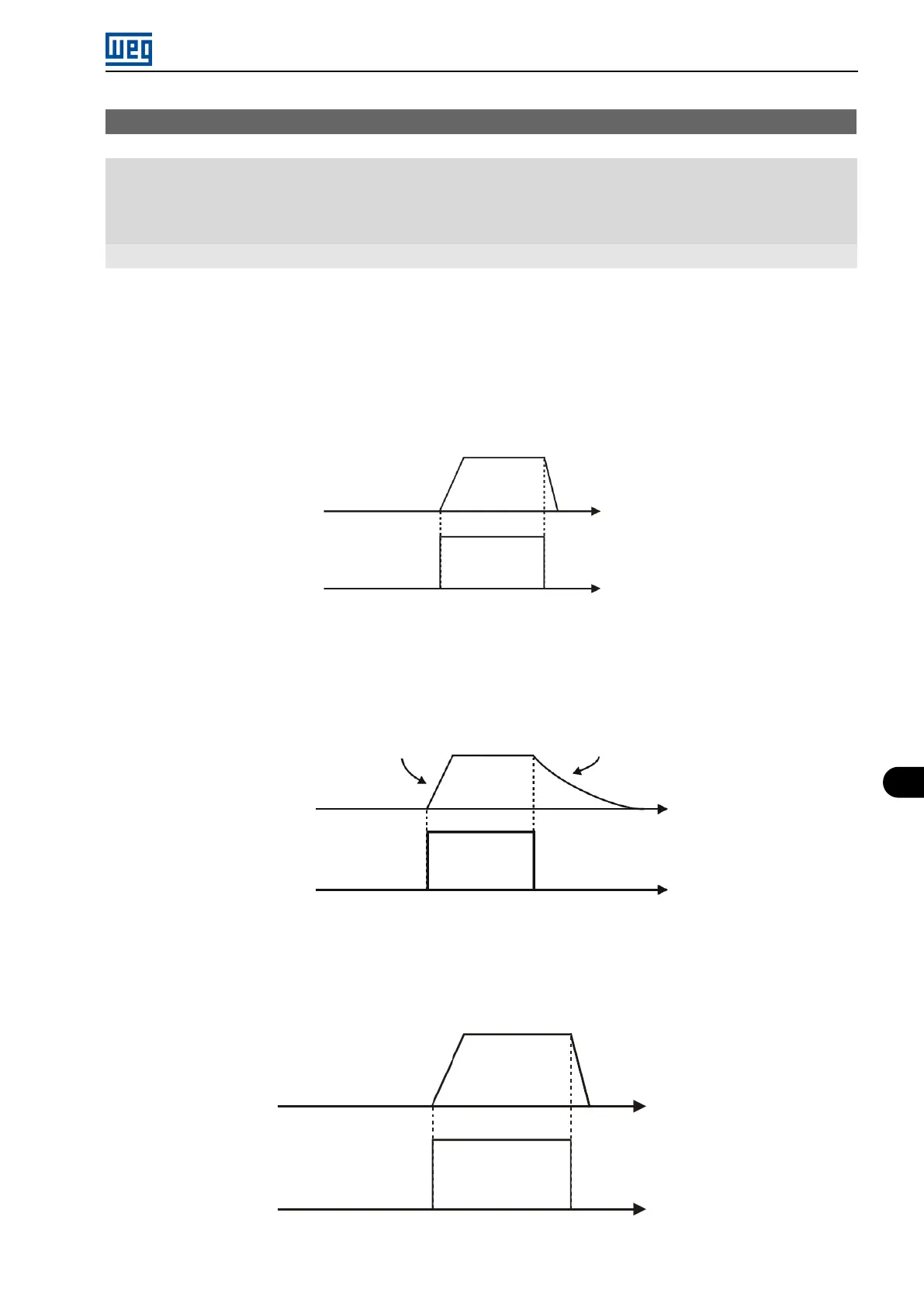
a) RUN/STOP
It enables or disables the motor rotation through the acceleration and deceleration ramp (Figure 9.6 on page
9-15).
Output
frequency
Acceleration
ramp
Deceleration
ramp
Time
Time
DIx
Inactive
Active
Figure 9.6: Example of the Run/Stop function
b) GENERAL ENABLE
It enables the motor rotation through the acceleration ramp and disables it by cutting off the pulses
immediately; the motor stops by inertia (Figure 9.7 on page 9-15).
Output
frequency
Acceleration ramp
Motor runs free
Time
Time
DIx
Inactive
Active
Figure 9.7: Example of the General Enable function
c) QUICK STOP
When inactive, it disables the inverter by the emergency deceleration (P107) (Figure 9.8 on page 9-15).
Output
frequency
Acceleration
ramp
P107 - Deceleration
ramp
Time
Time
DIx
Inactive
Active
Figure 9.8: Example of the Quick Stop function
Micro Mini Drives | 9-15