CFW501 | 19
Installation and Connection
English
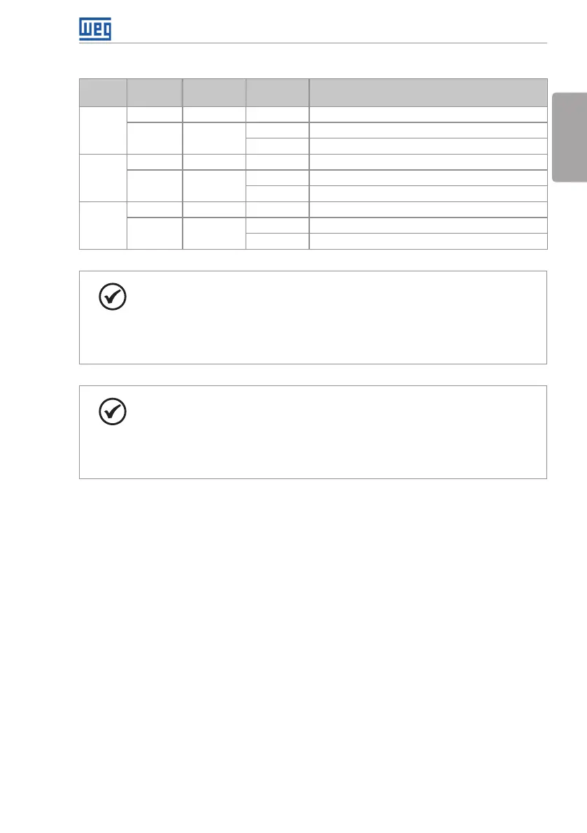
Table 3.2: Configuration of the switches to select the type of analog input and output signal on the
CFW500-CRS485
Input/
Output
Signal
Setting of
Switches
Signal
Range
Parameter Setting
AI1
Voltage S1.1 = OFF 0...10 V P0233 = 0 (direct reference) or 2 (inverse reference)
Current S1.1 = ON
0...20 mA P0233 = 0 (direct reference) or 2 (inverse reference)
4...20 mA P0233 = 1 (direct reference) or 3 (inverse reference)
AI2
Voltage S2.1 = OFF 0...10 V P0238 = 0 (direct reference) or 2 (inverse reference)
Current S2.1 = ON
0...20 mA P0238 = 0 direct reference) or 2 (inverse reference)
4...20 m A P0238 = 1 (direct reference) or 3 (inverse reference)
AO1
Voltage S1.2 = ON 0...10 V P0253 = 0 (direct reference) or 3 (inverse reference)
Current S1.2 = OFF
0...20 mA P0253 = 1 (direct reference) or 4 (inverse reference)
4...20 mA P0253 = 2 (direct reference) or 5 (inverse reference)
NOTE!
Configuration to connect the RS485:
S1.3 = ON and S1.4 = ON: terminal RS485 ON.
S1.3 = OFF and S1.4 = OFF: terminal RS485 OFF.
Any other combination of the switches is not allowed.
NOTE!
Configuration to connect the RS485:
S2.3 = ON and S2.4 = ON: terminal RS485(2) ON.
S2.3 = OFF and S2.4 = OFF: terminal RS485(2) OFF.
Any other combination of the switches is not allowed.