4 | CFW501
General Information
English
The frequency inverter CFW501 also has functions of PLC (Programmable Logic
Controller) by means of the SoftPLC (integrated) feature. For further details regarding
the programming of those functions, refer to the SoftPLC user's manual of the CFW501.
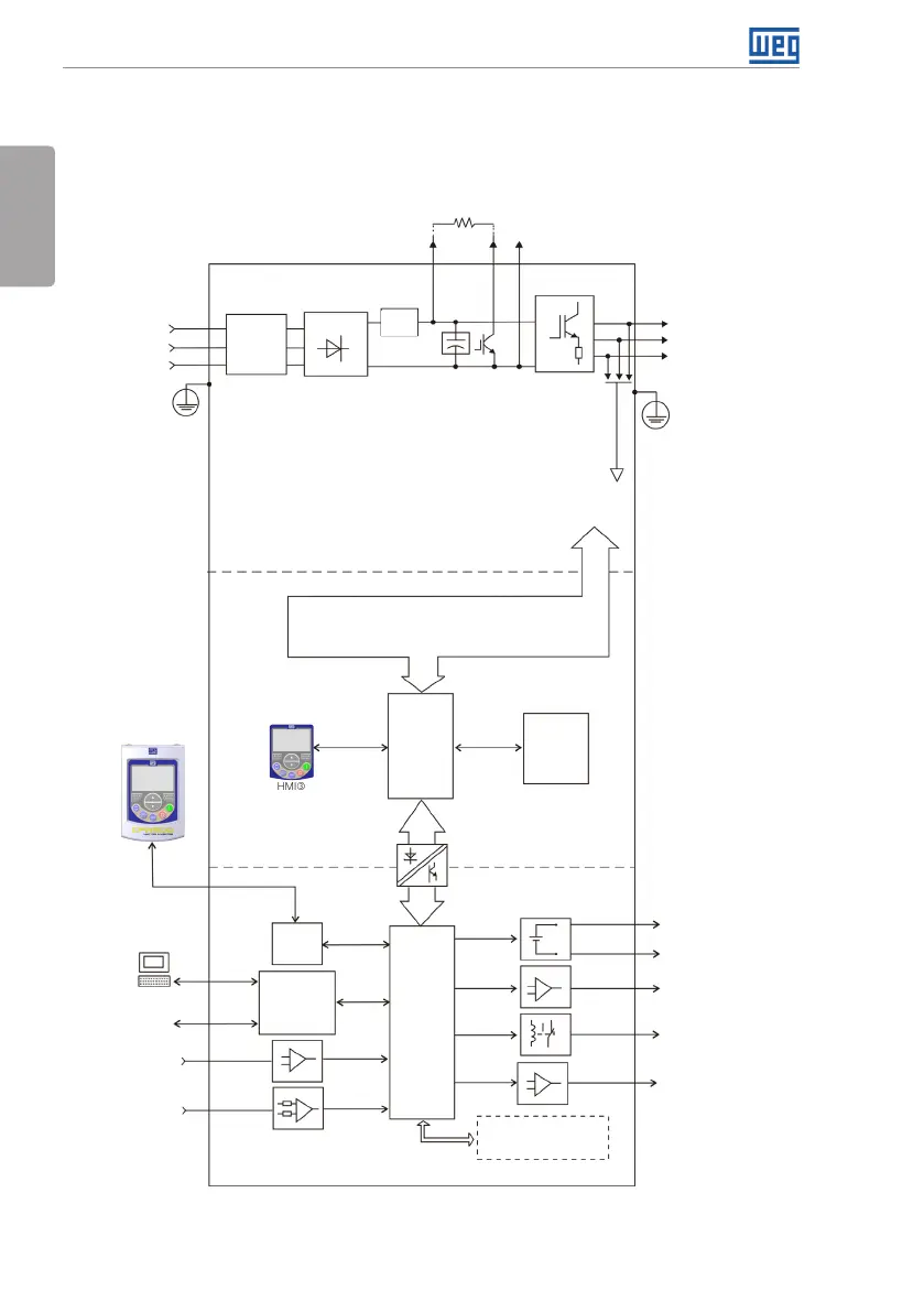
The main components of the CFW501 can be viewed in the block diagram figure 2.1
for Frames A, B and C, and figure 2.2 for Frame D.
Analog input
(AI1 and Ai2)
(*)
Digital inputs
(DI1 to DI4)
(*)
Supplies for electronics and interfaces
between power and control
RS-485
PC
POWER
Three-phase
rectifier
Internal
RFI filter
Motor
U/T1
V/T2
W/T3
DC+
DC-
BR
Inverter with
insulated gate bipolar
transistors and
current feedback
Power
supply
R/L1/L
S/L2/N
T/L3
= Bus connection CC
(**)
= Connection for brake resistor
(**)
Preload
Software WLP
SUPERDRIVE
(*)
MODBUS
Capacitor bank link CC
Braking IGBT (available in the inverters
CFW501...DB...)
HMI
CPU
32 bits
"RISC"
EEPROM
(memory)
User’s
plug-in
card
Interface
RS485
Analog
output
(AO1)
(*)
Power supply 24 V
Power supply 10 V
Digital output
DO1 (RL1) and
DO3 (RL2)
Digital output
DO2 (TR)
(*)
HMI (remote)
Power Supply
(**)
PE
PE
Memory Card (MCard)
Accessory
CONTROL
CONTROL
RS-485 PLUG-IN
= Human-machine interface
(*) The number of analog/digital inputs/outputs, as well as other resources, may vary according to the plug-in module used. For
further information, refer to the guide supplied with the accessory or the CD-ROM.
(**) Not available in frame A.
Figure 2.1: Block diagram of CFW501 for Frames A, B and C