LIFT
PUMP
SPEED
ACTUATOR
~
....----'
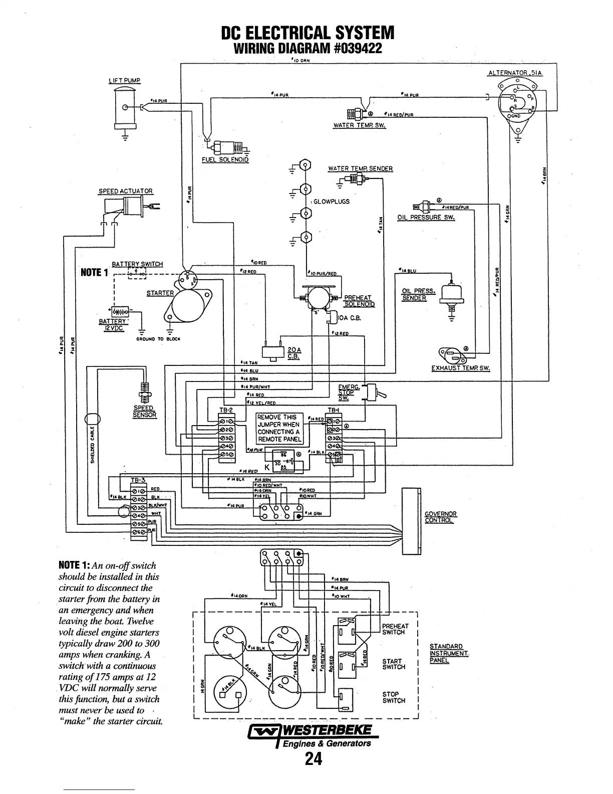
DC
ELECTRICAL
SYSTEM
WIRING
DIAGRAM
#039422
·-:-,...:
-~
FUEL
SOL
ENOl!}
10
ORN
~D
WATER
TEMP.
SENDER
-mlHn_
• ,
GLOWPLUGS
~D
~D
ll!M
IL
ll4AEO/P R
OIL
PRESsURE
SW.
BA
TT~RY
SWITCH
t10A£C
NOTE
1
.---.io-i..J------~-.r-),(P&:==;-j''!£!!
2
~{~o
*14AII
1
JOPUR
REn
I
'---~
foB
I
.2_
'{')J~
~D
OILPRESS.
~
SENDER
T
;
STAR!ER
J
·~n·l•-
BATTERY"
,lQ~·~~
12VDC
=
~
GROUND TO
BLOCIC
,
lOA
c.e.
......
e~
•14
BLU
i14
BRH
fl4
PUR/WHT r Q
G
C....
:::::~
R•n
~
~
TB·2J
~
~
r::R=:EM""O""'V:=E-:T'""HI-::-5-,
~5i0
,..._
_
_...,t'O~-''"'
"'~'-~
JUMPER
WHEN
H=::::;e~;;;---'
v~
EXHAUST
~EMP.
SW.
'---
;020
l.
CONNECTING
A
1~0+'@'-----,
l
~~~~)i$~~=t=f=t-----------~
~
REMOTE
PANEL
Lj:j:~-~=~:~:
'"""~
~·~£
....
'",~-.;;·:;.::.
__,IHH-t--'------------'
NOTE
1:
An
on-off
switch
should be installed in this
circuit to disconnect the
starter from the battery in
an emergency
and
when
leaving the boat. Twelve
volt diesel engine starters
typically draw
200
to300
amps when cranking. A
switch-with a continuous
rating
of
175
amps at 12
VDC will normally serve
his function, but a switch
must
never be used to
"make"
the starter circuit.
.,.1/EO
K I
>O~
I
#~BLK
••
.
WHT
114 8RN
•t•
PUR
ft4®N
~
'---1-:-
r
I I
I I
I I
I I
I
START
I
I
SWITCH
I
I 5 1
I %
STOP
l
I
SWITCH
I
I
~
I
L------;-.,.--,--
-------
---,-
..,---
_j
~
WESTERBEKE
Engines
&
Generators
24
STANDARD
INSTRUMENT.
PANEL
z
"'
"'
:;