User Guide
4. Management
4.9 Daisy Chaining
4.9
Daisy Chaining
This chapter provides information related to predefined daisy chaining configurations and specific
requirements.
4.9.1
Daisy Chaining Configurations
The Ultrastar Data60 supports configurations up to four enclosures daisy chained together using active
cables. The Daisy Chaining Key identifies the specific information needed to use the cable maps in the
following sections. The daisy chaining configurations are broken into two sections: one host configurations
and two host configurations. Each of the sections provide a list of the configurations and an example
diagram of how the enclosures can be connected using SAS cables.
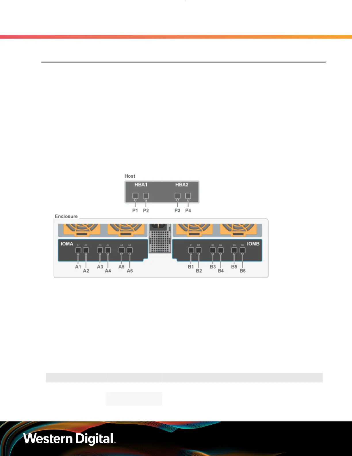
The following diagram identifies the host, host ports, IOM configuration, and IO SAS connections.
Figure 208: Daisy Chaining Key
The following section identifies the different host configurations for daisy chaining multiple enclosures with
either one or two hosts.
One Host Configurations: The following diagram is an example of how the enclosures will be connected
via the IO SAS ports and what number each enclosure is. This information can be utilized with this cable
map: One Host Cable Configurations (page 222).
Two Host Configurations: The following diagram is an example of how the enclosures will be connected
via the IO SAS ports and what number each enclosure is. This information can be utilized with this cable
map: Two Host Cable Configurations (page 227).
Table 51: Daisy Chaining Configurations
Type of Enclosure Number of Hosts Number of HBAs per Host Number of Enclosures
1
SAS
2
1 HBA 2-4
221

 Loading...