page 3 – 2
D-5000 / May 2000
STEREO LINE INPUT
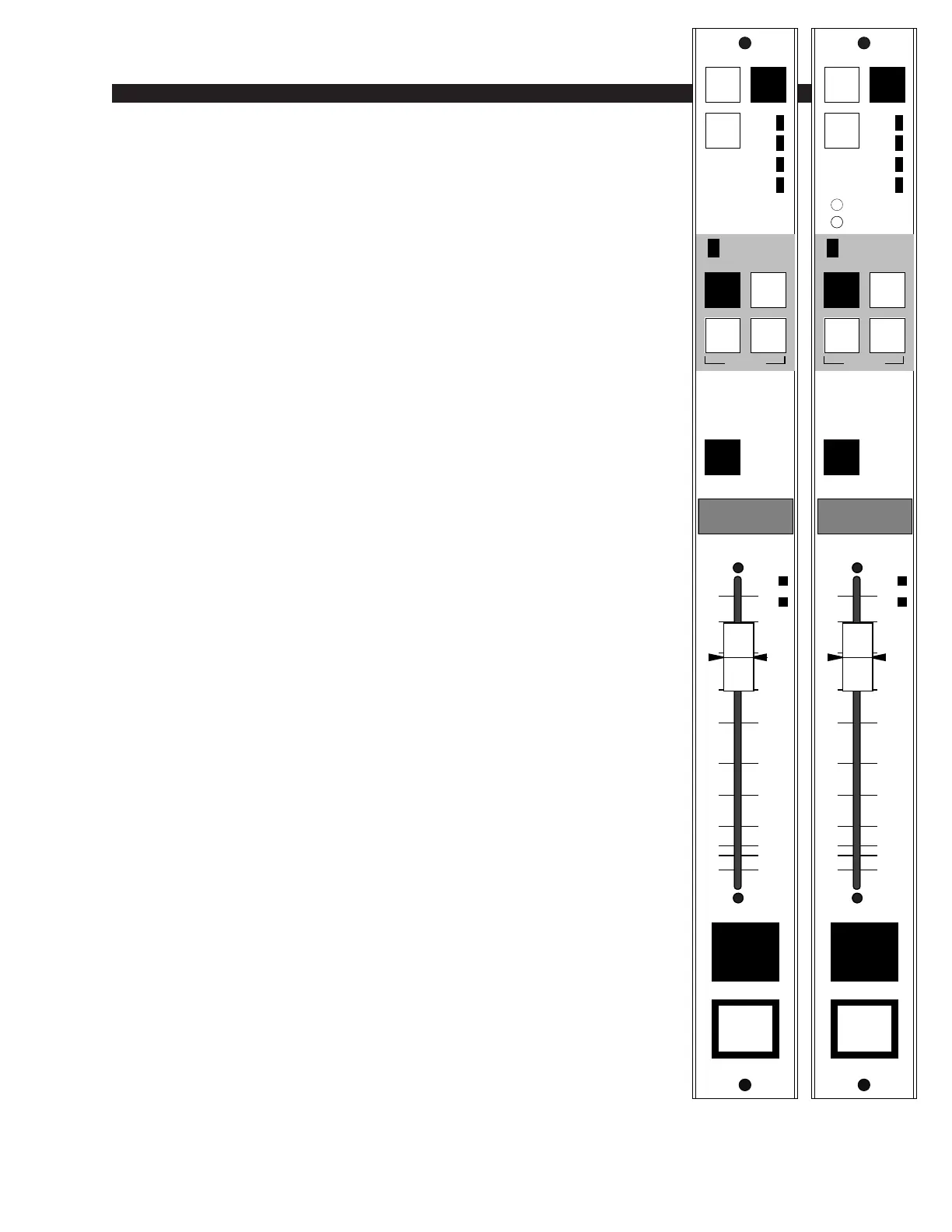
Stereo Line Input (SLD-600)
Module Overview
SLD-600 modules are for stereo line input signals. They are
available in two different versions:
The ADC (analog-to-digital converter) version accepts +4dBu balanced
analog input signals. It has L/R front panel input gain trimpots and uses an
SLADC-600 piggyback card at the input stage of the module.
The SRC (sample rate converter) version accepts digital (AES) inputs. It
uses an SRC-500 piggyback input card and has no front panel gain trims.
The factory default digital format is AES.
Each module accepts two stereo sources: A and B, switched at the
top of the module. The MODE SELECTION enables the module to
operate in stereo, mono, left only, or right only. The MODE button
illuminates red when set to STEREO; MONO (L+R to both channels),
LEFT to both channels, and RIGHT to both channels. Being electronic,
mode selection is lossless and click-free. When in MONO mode
automatic gain compensation occurs to offset mono summation.
Output switches assign the selected source signal to any combina-
tion of the console’s four stereo outputs: PGM (program), AUD
(audition), AUX (auxiliary) and/or UTL (utility). When the module is
assigned to PGM and turned ON, a red “On-Air” LED illuminates just
above the output assign switches.
A CUE switch places the module’s signal on the console’s stereo
cue bus, where it may be heard on the meterbridge mounted cue
speakers and/or as an interrupt to the console operator’s headphones
and control room monitor speakers. The various cue interrupt modes
are programmed at the console’s CRD-600 (Control Room) module via
internal PCB-mounted dipswitches. See page 5-3.
Level is set by a Penny & Giles long-throw fader. When the D-5000
is under external serial control from an automation system, the Fader
Null LEDs show which direction the fader must move for manual
override.
Channel ON (START) and OFF (amber) switches are at the bottom
of the module. In addition to being controlled remotely, these can also
be programmed (via VDIP program) to perform a variety of functions,
including activating control room and studio mutes, external tallies,
and timer restart. The OFF switch’s LED can be controlled by an
external source machine to act as a “ready” indicator.
All audio and control input and output signals are made via two
multi-pin DB-25 connectors mounted in the bottom of the console’s
mainframe, directly underneath each individual module.
CUE
AUD
AUX
UTL
MODE
A
B
PGM
–
+
FDR
NULL
0
5
10
15
20
30
40
ASSIGN
ON AIR
LT
R
STEREO
MONO
START
CD-1
STEREO INPUT
START
CUE
AUD
AUX
UTL
MODE
A
B
PGM
LINE TRIM
L
R
–
+
FDR
NULL
0
5
10
15
20
30
40
ASSIGN
ON AIR
LT
R
STEREO
MONO
START
CD-1CD-1
STEREO INPUT
SLD-600/SRC SLD-600/ADC
D-5000 / May 2001