page 7 – 2
D-5000 / May 2000
METER OUTPUT MODULE
Meter Output Module
(MOD-600)
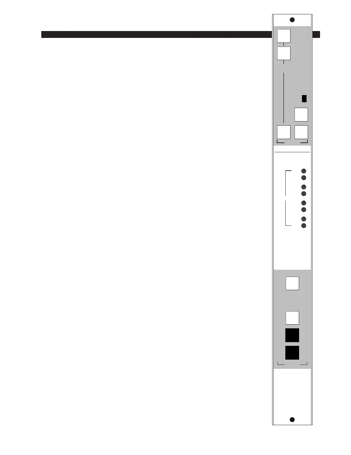
Module Overview
Each D-5000 console has one meter output module, which drives the
console’s up to four pairs of left-right VU meters: PGM, AUD, AUX and
SWT (switched). The switched meter follows the SELECT switching at
the top of the module, allowing the console operator to meter AUD, AUX,
UTL and two external stereo line signals (analog, +4dBu balanced) which
may be brought into the module on its lower DB-25 connector.
The MOD-600 module also houses the master CUE LED indicator.
Whenever Cue is activated anywhere on the console this LED will
illuminate and the CUE signal will automatically appear on the switched
VU meter pair. When cue is de-activated, the switched meter pair goes
back to it’s previously selected signal.
Recessed front panel trim pots calibrate up to four meter pairs. A VU
TRIM cover strip (not shown) can be used to prevent trimpot access once
calibration is set.
At the bottom of the module are the timer control buttons (the timer
display is mounted in the righthand end of the console meterbridge):
AUTO – enables timer restart functions from programmed input modules
S/S – Start/Stop
RESET - return to zero (if the timer is stopped it will hold at zero; if it is
running it will reset to zero and immediately begin counting up).
HOLD – when held down freezes the timer display (the counter keeps on
going); when released the display catches up to the current count.
All user wiring to and from the MOD-600 module takes place at the
lower DB-25 multi-pin connector mounted directly beneath the module on
the console mainframe’s bottom pan. This lower connector (near the
console armrest) inputs the module’s two external stereo line signals. See
the pinout drawing on page 7-4.
While there are two DB-25 connectors, the upper one (towards the console
meterbridge) is for factory use only. It sends the module’s VU and timer control
signals to the meterbridge (a factory-provided cable runs from this upper DB-25
to a matching connector mounted at the back of the meterbridge, in the center of
the console).
TIMER
RESET
S / S
HOLD
AUTO
1
2
EXTERNAL
STEREO
AUD
SELECT
AUX UTL
LT
R
PGM
LT
R
AUD
LT
R
AU
CUE
SWITCHED VU
VU TRIM
LT
R
SWT