page 6 – 4
D-5000 / May 2000
STUDIO CONTROL MODULE
Hook-Ups
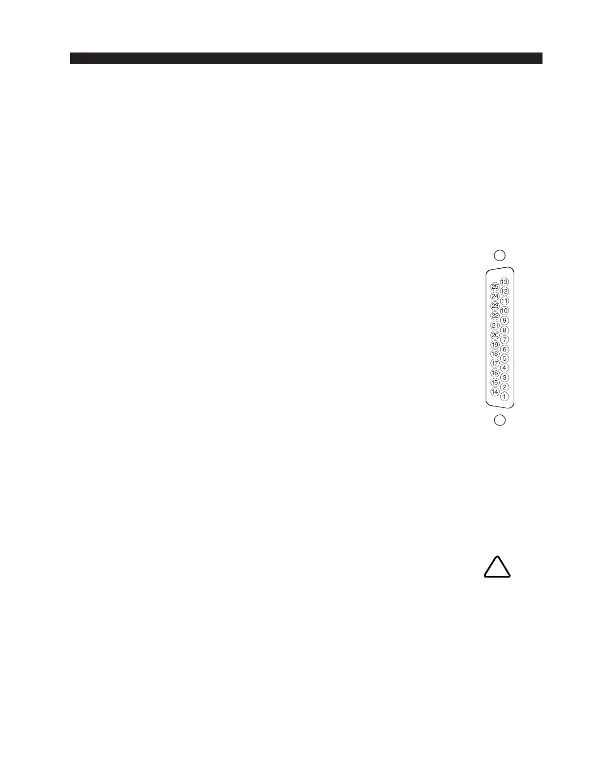
As stated before, all user wiring to and from the SCD-600 module takes
place at two DB-25 multi-pin connectors mounted directly beneath the
module on the console mainframe’s bottom pan.
Upper DB-25 Connector — Audio
Includes studio 1, studio 2 and (mono) talkback outputs. All audio
signals are analog, +4dBu balanced.
Pin 25 – TB Out SH
Pin 24 – TB Out HI
Pin 12 – TB Out LO
Pin 22 – Lt Studio 2 Out SH
Pin 21 – Lt Studio 2 Out HI
Pin 9 – Lt Studio 2 Out LO
Pin 8 – Rt Studio 2 Out SH
Pin 7 – Rt Studio 2 Out HI
Pin 20 – Rt Studio 2 Out LO
Pin 19 – Lt Studio 1 Out SH
Pin 18 – Lt Studio 1 Out HI
Pin 6 – Lt Studio 1 Out LO
Pin 5 – Rt Studio 1 Out SH
Pin 4 – Rt Studio 1 Out HI
Pin 17 – Rt Studio 1 Out LO
Upper DB-25 Connector — Control
The console’s Tally 2 and Tally 3 control ports are on the SCD-600
upper DB-25 connector. These are simple relay closures that activate
whenever programmed input modules are turned ON (see page 2-4). The
ports can be used to control externally powered tally lights that requires a
continuous closure to function.
Pin 14 – Tally 2 Relay COM
Pin 1 – Tally 2 Relay N.O.
Pin 3 – Tally 3 Relay COM
Pin 15 – Tally 3 Relay N.O.
Maximum current through
the tally relay closures is
2 amps @30VDC.
!
Typical DB-25
connector