page 4 – 2
D-5000 / May 2000
OUTPUT MODULES
Output Modules
(OMD-600)
Module Overview
Each D-5000 console has two master output modules: the
first handles the console’s Program and Auxiliary outputs
(MASTER A), and the second handles Audition and Utility
(MASTER B).
MASTER A output module has installed jumpers J3, J4
for Program output; J7, J8 for Auxiliary output; and J11, J12
for CUE monitor signal.
MASTER B output module has installed jumpers J5, J6
for Audition output; J9, J10 for Utility output; and J13, J14 for
TEL monitor signal.
Either module can be changed to the other by making the
appropriate jumper changes.
Both modules output analog and digital signals. Analog
outputs may be adjusted using recessed front panel multi-turn
trimpots.
OMD-600 modules also generate the console’s monitor
signals, which feed the Control Room, Studio and Meter
Output modules. There are analog stereo insert points for
PGM and AUD analog outputs (these may be internally
bypassed, which is the factory default setting). Processing
done at the insert points will not affect the digital output
signals. Regardless of the bypass switch setting, INSERT
OUT may be used as an additional direct PGM (or AUD)
analog output from a module.
All user wiring to and from the OMD-600 modules takes
place at DB-25 multi-pin connectors mounted directly be-
neath the module on the console mainframe’s bottom pan.
There are two connectors: the upper one (towards the console
meterbridge) handles analog outputs and insert points; the
lower connector (near the console armrest) handles digital
outputs (AES format). All analog audio is +4dBu balanced.
Pinout drawings on pages 4-6 and 4-7 show all wiring
connections at a glance.
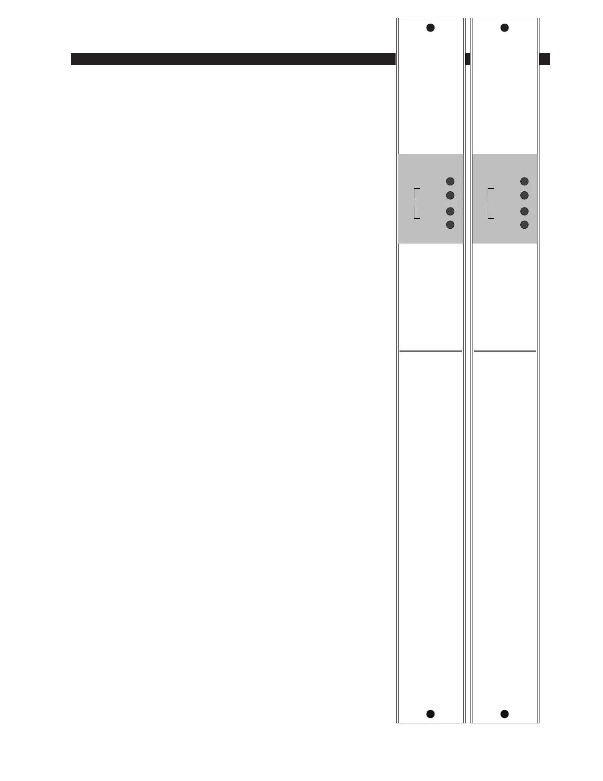
ANALOG TRIMS
LT
R
PGM
LT
R
AU
GAIN
MASTER A
ANALOG TRIMS
LT
R
AUD
LT
R
UTL
GAIN
MASTER B