page 10 – 6
D-5000 / May 2000
SUPERPHONE INPUT
Hook-Ups
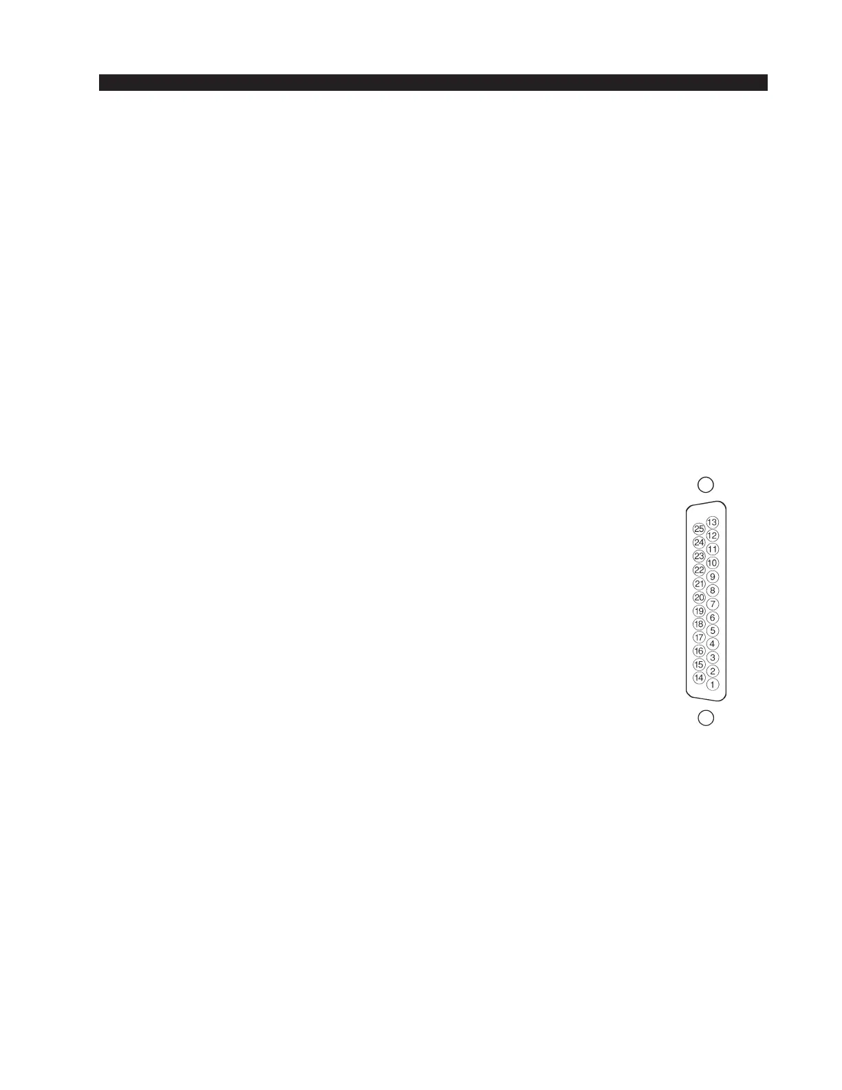
As stated before, all user wiring to and from SPD-600 modules takes
place at DB-25 multi-pin connectors mounted directly beneath each module
on the console mainframe’s bottom pan. There are two connectors per
module: the upper one (towards the console meterbridge) handles audio
input signals; the lower (near the console armrest) audio outputs and control
signals. A pinout drawing on page 10-8 shows all wiring connections at a
glance.
Audio Connections (upper DB-25)
These include External In and station Hybrid 1 & 2 inputs. All are +4dBu
balanced analog mono.
Pin 25 – Ext In SH
Pin 24 – Ext In HI
Pin 12 – Ext In LO
Pin 22 – Hybrid 1 In SH
Pin 21 – Hybrid 1 In HI
Pin 9 – Hybrid 1 In LO
Pin 8 – Hybrid 2 In SH
Pin 7 – Hybrid 2 In HI
Pin 20 – Hybrid 2 In LO
Pins 2,5,11,13,16 and 19 – Audio Ground
Audio and Control Connections (lower DB-25)
These include outputs to the station hybrid, module output composite
feeds (for recording) and remote tape machine START/STOP ports.
Pin 25 – Composite Out SH
Pin 24 – Composite Out HI
Pin 12 – Composite Out LO
Pin 11 – Composite Minus Callers Out SH
Pin 10 – Composite Minus Callers Out HI
Pin 23 – Composite Minus Callers Out LO
Pin 22 – Callers Only Out SH
Pin 21 – Callers Only Out HI
Pin 9 – Callers Only Out LO
Pin 8 – To Hybrid 1 Out SH
Pin 7 – To Hybrid 1 Out HI
Pin 20 – To Hybrid 1 Out LO
Pin 19 – To Hybrid 2 Out SH
Pin 18 – To Hybrid 2 Out HI
Pin 6 – To Hybrid 2 Out LO
Typical DB-25
connector