page 3 – 3
D-5000 / May 2000
STEREO LINE INPUT
Internal Programming Options
There are no internal programming options on the SLD-600 module.
VDT Programming Options
Mutes, timer restart, cue dropout, local/ready, tallies, superphone
output assign, utility bus pre-fader, remote on/off-constant vs. pulse, and
remote start/stop-normal vs. EFS programming are made via Virtual Dip
Switch Software (see Chapter 9).
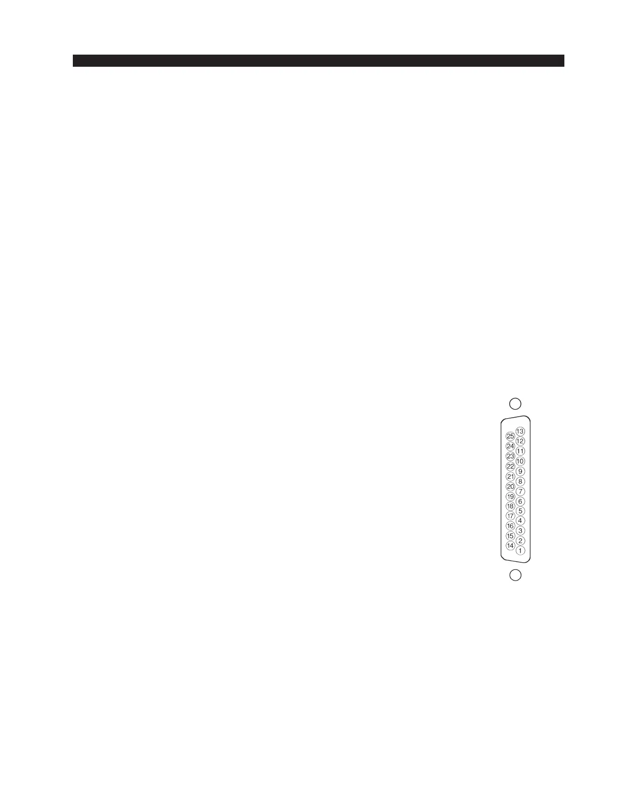
Hook-Ups
As stated before, all user wiring to and from SLD-600 modules takes
place at DB-25 multi-pin connectors mounted directly beneath each
module on the console mainframe’s bottom pan. There are two connectors
per module: the upper one (towards the console meterbridge) handles
audio inputs; the lower (near the console armrest) control signals. Pinout
drawings on pages 3-6 and 3-7 show all wiring connections at a glance.
ADC Module Version (Analog)
Audio Connections (upper DB-25)
These include A and B source inputs; level is +4dBu balanced.
Pin 25 – Line A In Lt SH
Pin 24 – Line A In Lt HI
Pin 12 – Line A In Lt LO
Pin 11 – Line A In Rt SH
Pin 10 – Line A In Rt HI
Pin 23 – Line A In Rt LO
Pin 22 – Line B In Lt SH
Pin 21 – Line B In Lt HI
Pin 9 – Line B In Lt LO
Pin 8 – Line B In Rt SH
Pin 7 – Line B In Rt HI
Pin 20 – Line B In Rt LO
SRC Module Version (Digital)
Audio Connections (upper DB-25)
These include A and B source inputs (AES).
Pin 25 – Line A In SH
Pin 24 – Line A In HI
Pin 12 – Line A In LO
Pin 11 – Line B In SH
Pin 10 – Line B In HI
Pin 23 – Line B In LO
?
Typical DB-25
connector
In passing, the three 4-
position dipswitches
(SW1, SW2 and SW3)
mounted in the middle of
the SRC-500 piggyback
card are for factory use
only. Do not disturb their
settings!
D-5000 / Feb 2002