page 3 – 4
D-5000 / May 2000
STEREO LINE INPUT
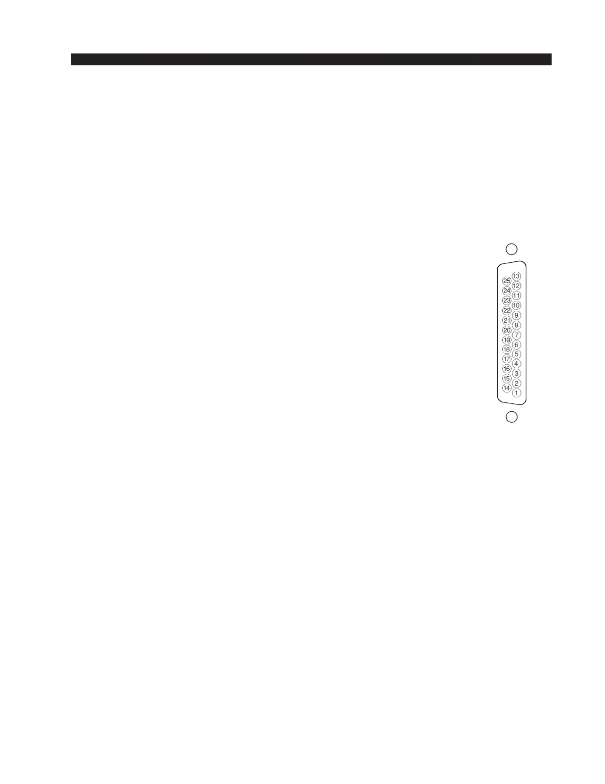
Control Connections (lower DB-25)
These are identical for both analog and digital versions of the SLD-600
module. All control ports (except On Tally) are opto-isolated. Functions
include remote on and off, on tally, ready, and start/stop for remote source
machines. With the exception of On Tally, each function is available twice,
for both A and B source ports, allowing it to follow the module's A/B
source selector switch.
Pin 1 – Ready A-
Pin 2 – Ready A+
Pin 3 – Start A+
Pin 4 – Stop A+
Pin 5 – Start/Stop Com A
Pin 6 – Start/Stop Com B
Pin 7 – Stop B+
Pin 8 – Start B+
Pin 9 – Ready B+
Pin 10 – Ready B-
Pin 11 – Digital Ground
Pin 12 – On Tally
Pin 13 – +5V Digital
Pin 14 – Remote On A-
Pin 15 – Remote On A+
Pin 16 – Remote Off A-
Pin 17 – Remote Off A+
Pin 18 – Remote Off B+
Pin 19 – Remote Off B-
Pin 20 – Remote On B+
Pin 21 – Remote On B-
To Turn the Module ON & OFF from a Remote Location
In the case of stereo line input modules, “remote location” can also
refer to a remote source machine that is feeding its audio to the module in
question. A 5VDC signal, as indicated below, will activate the module’s
channel ON and OFF switches.
REMOTE ON — Activates the module’s channel ON switch. Provide
a momentary 5VDC signal between Pins 14 and 15 (Remote On A) or Pins
20 and 21 (Remote On B). This will latch the module ON. Be sure to
observe the polarity as indicated on the pinout diagram on pages 3-7, 3-8.
REMOTE OFF — Activates the module’s channel OFF switch.
Provide a momentary 5VDC signal between Pins 16 and 17 (Remote Off
A) or Pins 18 and 19 (Remote Off B). This will latch the module OFF. Be
sure to observe the polarity as indicated on the pinout diagram on pages
3-7, 3-8.
Typical DB-25
connector
D-5000 / Feb 2002