page 4 – 4
D-5000 / May 2000
OUTPUT MODULES
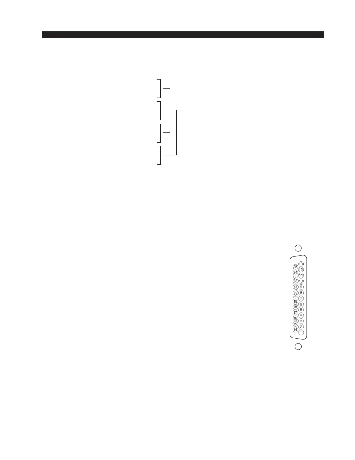
Typical DB-25
connector
Lower DB-25 Connector – Digital Outputs
Handles digital Program and Auxiliary outputs
Pin 8 – AUX2 AES Out SH
Pin 7 – AUX2 AES Out HI
Pin 20 – AUX2 AES Out LO
Pin 19 – PGM2 AES Out SH
Pin 18 – PGM2 AES Out HI
Pin 6 – PGM2 AES Out LO
Pin 16 – AUX1 AES Out SH
Pin 15 – AUX1 AES Out HI
Pin 3 – AUX1 AES Out LO
Pin 2 – PGM1 AES Out SH
Pin 1 – PGM1 AES Out HI
Pin 14 – PGM1 AES Out LO
Master Output Module B:
Upper DB-25 Connector – Analog Audio
Includes Audition, Utility outputs and Audition insert points. All signals
are +4dBu balanced.
Pin 25 – AUD Lt Out SH
Pin 24 – AUD Lt Out HI
Pin 12 – AUD Lt Out LO
Pin 11 – AUD Rt Out SH
Pin 10 – AUD Rt Out HI
Pin 23 – AUD Rt Out LO
Pin 22 – UTL Lt Out SH
Pin 21 – UTL Lt Out HI
Pin 9 – UTL Lt Out LO
Pin 8 – UTL Rt Out SH
Pin 7 – UTL Rt Out HI
Pin 20 – UTL Rt Out LO
Pin 19 – AUD Lt Insert Out SH
Pin 18 – AUD Lt Insert Out HI
Pin 6 – AUD Lt Insert Out LO
Pin 5 – AUD Rt Insert Out SH
Pin 4 – AUD Rt Insert Out HI
Pin 17 – AUD Rt Insert Out LO
Pin 16 – AUD Lt Insert In SH
Pin 15 – AUD Lt Insert In HI
Pin 3 – AUD Lt Insert In LO
Pin 2 – AUD Rt Insert In SH
Pin 1 – AUD Rt Insert In HI
Pin 14 – AUD Rt Insert In LO
Insert points are normally by-
passed at the factory. See “In-
sert Bypass” (preceding page) if
you intend to use these points.
D-5000 / Sep 2000
AUX1 & AUX2
Duplicate outputs
PGM1 & PGM2
Duplicate outputs