page 10 – 2
D-5000 / May 2000
SUPERPHONE INPUT
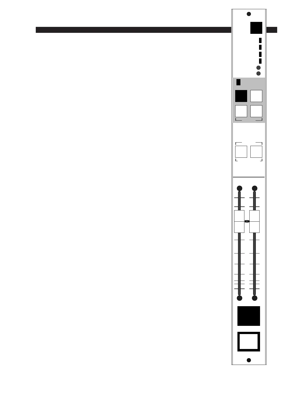
Superphone Input (SPD-600)
Module Overview
SPD-600 input modules are used for telephone call-ins. Each module
can handle two callers; there can be two modules per console for a total of
four callers. Caller signals enter the module from your station hybrid; each
caller has his own fader. Caller input gain trims are provided at the top of
the module.
Output switches assign callers to any combination of the console’s four
stereo outputs: PGM (program), AUD (audition), AUX (auxiliary) and/
or UTL (utility). When the module is assigned to PGM and turned ON, a
red “On-Air” LED illuminates just above the output assign switches.
Caller Set-Ups
Pre-air segment communication between the console operator (DJ)
and callers is via CALLER SETUP buttons (2) which place the caller’s
voice on the console’s cue speakers (or control room speakers/operator’s
headphone if the CRD-600 module’s cue interrupt function has been so
programmed). These cue signals can be internally programmed pre or post
fader.
The caller hears the DJ in one of two ways:
1) The DJ can assign his microphone input module to an unused output
bus—say UTL—and the DJ then selects the UTL input with the MIX
MINUS SOURCE switch at the top of the phone module. This sends a
dedicated (digitally generated) version of the UTL bus signal to the SPD-
600 module’s hybrid output, where it is ultimately heard by the caller
through his telephone. This mix minus source select method can also be
used to preplay a musical segment (or any other program content) for the
caller off-air. Take the SLD-600 input module handling the desired music
cut and assign it to an unused output bus; select the same bus as the caller’s
mix minus source input and he will hear it off-air.
Remember MMD-600 microphone input modules can be internally pro-
grammed to have their Utility bus feed tapped pre-fader, pre-ON/OFF, making
this a logical set-up for the DJ’s mic input if you do a lot of call-in work, since
the DJ’s voice will always be present on the console’s Utility output bus
regardless of fader or ON/OFF settings on his mic module (which must still be
assigned to UTL, however).
2) The DJ’s voice signal can be inputted through a special EXT IN port
at the SPD-600 module’s DB-25 connector. This second method elimi-
nates the need to select a mix minus input source everytime you want to
talk off-air to the caller. An easy source choice here would be DJ mic
module’s INSERT OUT port.
MIX MINUS
SOURCE
0
5
15
20
30
40
50
60
70
00
10
ON
INPUT
12
PGM
AUD
AUX UTL
ASSIGN
SETUP TB / CUE
CALLERS
ON AIR
CALLER TRIM
1
2
AU
UTL
PGM
AUD
12
CALLER INPUT