41
4. For the Service Technician
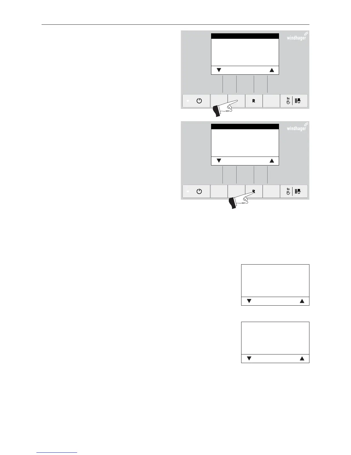
Fig. 87
Values
Parameters
Actuator test
Settings
Choose Back
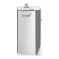
Fig. 88
Values
Parameters
Actuator test
Settings
Choose Back
Select the required item, „Values“, „Parameters“, „Ac-
tuator test“ or „Settings“ and confirm by pressing the
Choose button – Fig. 87.
For further settings, see sections 4.7.1 - 4.7.4.
The menu item or sub-menu item is exited by pressing
the Back button or after a delay of 10 minutes – Fig. 88.
4.7.1 Values
The following values are displayed:
Temp. Boiler
The current boiler temperature is displayed in °C.
Temp. chamb.
The current temperature in the combustion chamber is displayed in °C.
Fan-speed
The nominal speed of the blower is displayed in rpm.
Pos. Prim. airfl.
The position of the primary air choke is displayed in %.
Pos. Sec. airfl.
The position of the secondary air choke is displayed in %.
O2 signal
The O2 signal of the lambda sensor is displayed in %.
O2 heat current
The O2 heat current of the lambda sensor is displayed in A.
Temp. Exhaust
The current flue gas temperature is displayed in °C.
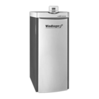
Fig. 89
Temp. Boiler 68°C
Temp. chamb. 578°C
Fan-speed 2500 rpm
Pos. Prim. airfl. 60%
Pos. Sec. airfl. 30%
O2 signal 18,1%
Back
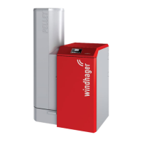
Fig. 90
O2 heat current 2,5A
Temp. Exhaust 195°C
Back