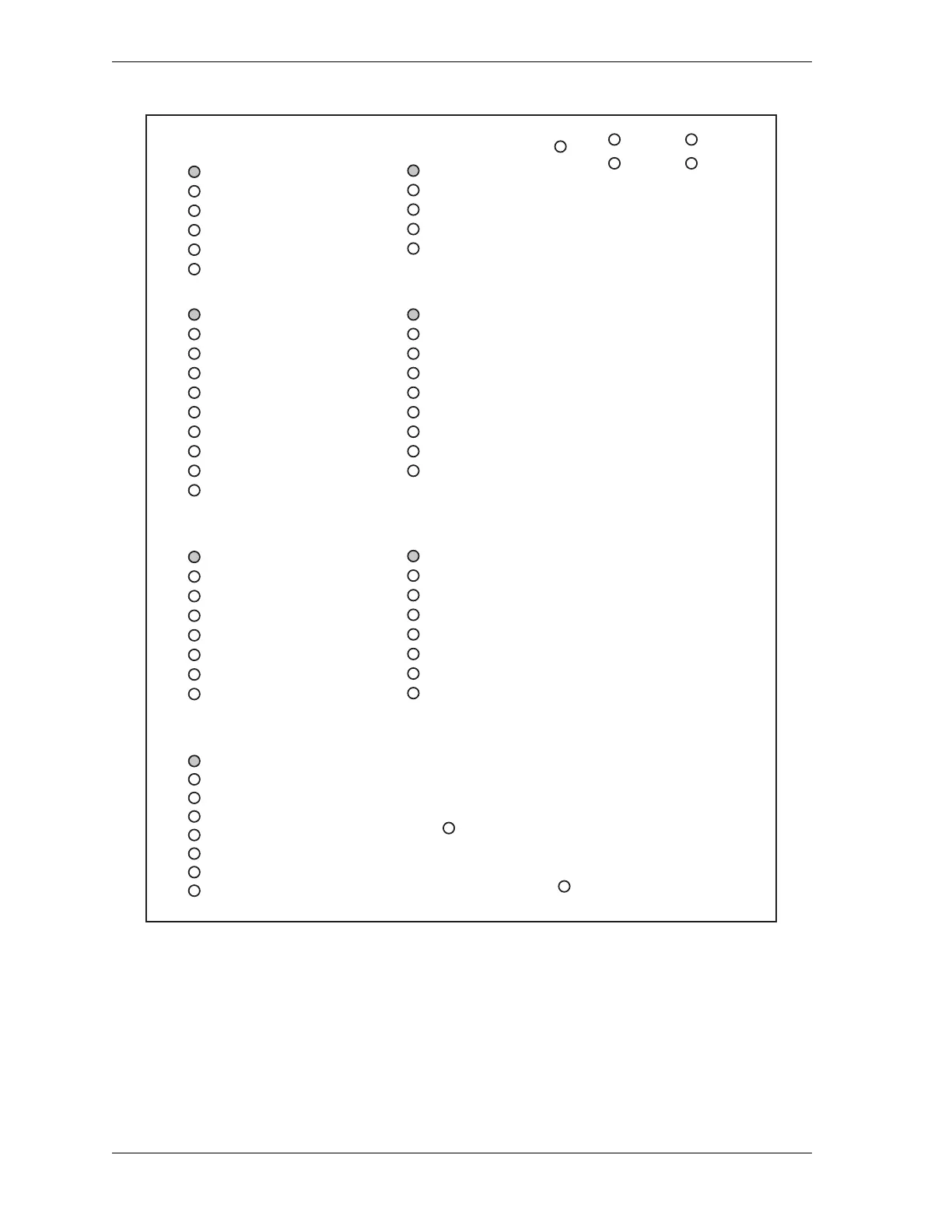
Figure 3-15. WPC 2000 LED Indicator Map (Left-mounted Board)
G
R
O
U
P
7
77 - Light curtain A 1 input
87 -
Light curtain A 2 input
82 - User input 2
83 - User input 4
84 -
User input 6
85 -
User input 8
86 -
User input 10
76 - Mute lamp 2 output
G
R
O
U
P
6
24 - Overrun limit switch
26 - Unused input
70 - Remote reset
71 - User input 3
72 - User input 5
73 - User input 7
74 - User input 9
75 - Unused input
G
R
O
U
P
5
DSV A drive check
Lockout contact check
Lockout drive check
DSV B drive check
DSV A contact check
88 - Light curtain B 2 input
DSV B contact check
66 - Mute lamp 1 output
+ 24 VDC
Display bus Serial port
Receive
Transmit
Transmit
Receive
+ 5 Logic A
+ 5 Logic B
G
R
O
U
P
4
13 - Top stop inch disable
60 -
Top stop B2 input
16 - Bar actuator input
17 - Motor reverse input
18 - User input 11
19 - Unused input
63 - Prior act B input
22 - Top stop limit switch
57 - E-stop B2 input
20 - DSV monitor input
G
R
O
U
P
3
12 - Palm switch B N/O
14 - Foot switch N/O
15 - Automatic actuator N/C
Aux B contact check
Aux A contact check
Aux A drive check
Aux B drive check
21 - User input 1
11 - Palm switch A N/O
All LEDs are red except ones that are
shaded, which are green. Pin numbers
associated with LEDs are shown in
bold. LEDs without pin numbers are
for internal connections. LED positions
on board are represented schematically.
2 - Palm switch B N/C
3 - One hand A
48 -
E-stop B1 input
5 - Automatic
actuator N/O
6 -
Bar selector switch
52 -
Top stop B1 input
G
R
O
U
P
1
1 - Palm switch A N/C
4 -
Foot switch N/C
7 -
Motor forward
78 -
Light curtain B 1 input
8 -
Clutch air pressure sw.
G
R
O
U
P
2