WPC 2000 User Manual 1128500
Installation 2-63
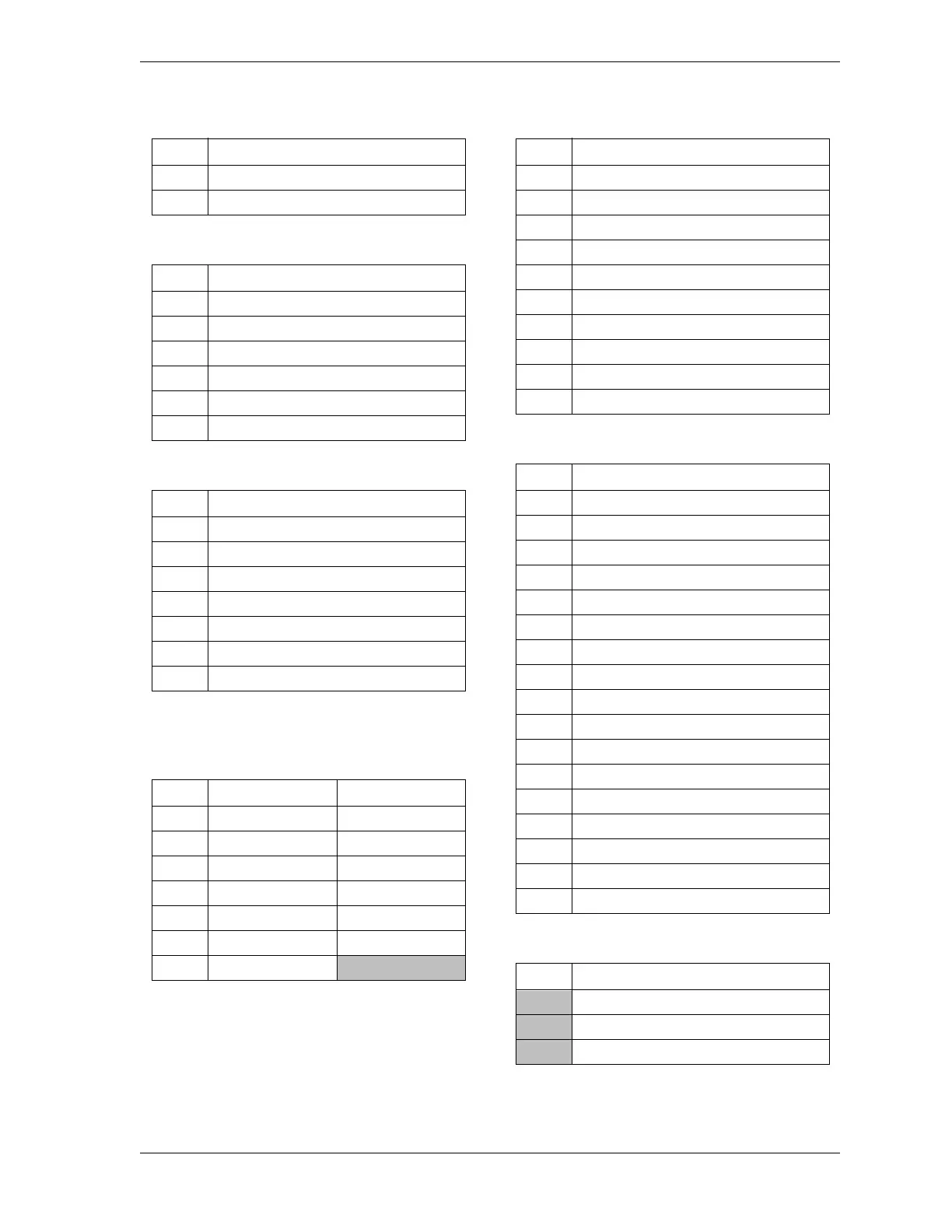
Table 2-18. Power Supply (TB105) Wiring
Pin #
Signal
90 +24 Vdc input
89 COM
Table 2-19. Aux. E-stop Relay Board Wiring
Pin #
Signal
96 Circuit 3 output
95 Circuit 3 input
94 Circuit 2 output
93 Circuit 2 input
92 Circuit 1 output
91 Circuit 1 input
Table 2-20. DSV/Lockout Relay Board Wiring
Pin #
Signal
103 DSV B relay output
102 DSV B relay input
101 DSV A relay output
100 DSV A relay input
99 Lockout relay output
98 Lockout relay output
97 Lockout relay input
Table 2-21. Resolver (TB 106) Wiring
CW (clockwise) rotation shown, viewing shaft end.
For CCW, reverse black and yellow wires.
Pin #
Signal Wire Color
104 S4 Return Brown
105 R2 Ground Orange
106 S3 Return Yellow
107 R1 Drive Red
108 S2 Cosine Green
109 S1 Sine Black
110 Shield
Table 2-22. Cam Outputs (TB 109) Wiring
Pin #
Signal
130 Cam 1
129 Cam 2
128 Cam 3
127 Cam 4
126 Counter
125 Zero cam
124 Spec 1
123 Spec 2
122 Ground
121 +24 Vdc
Table 2-23. Display Board Wiring
Pin #
Signal
157 Micro-inch selector input –
156 Cams selector input –
155 Ground
154 Operator station 1 selector input –
153 Operator station 2 selector input –
152 Ground
151
External/Two break selector input –
150 Ground
149 One hand selector input –
148 Foot selector input –
147 Spare selector input –
146 Ground
145 Off selector input –
144 Inch selector input –
143 Single-stroke selector input –
142 Continuous selector input –
141 Ground
Table 2-24. AC Power Wiring
Pin #
Signal
L1 (Hi)
L2 (Neutral)
Ground