WPC 2000 User Manual 1128500
Installation 2-21
• Do not try to couple the resolver directly to the crankshaft. Such a placement requires
extreme precision. If the resolver is only slightly off-center, its bearing will be subjected to
side loads well in excess of its rated capacity and will ultimately fail.
• Do not use flexible couplings, which can be inaccurate, or V belts, which can also be
inaccurate and will slip
• Do not use a flexible shaft like a speedometer cable. The resolver will lag the crankshaft
because of the twisting of the shaft on start-up. When the crankshaft stops, the resolver will
turn past the true stopping point and snap backward.
Mounting the Resolver
To mount the resolver, perform the following steps:
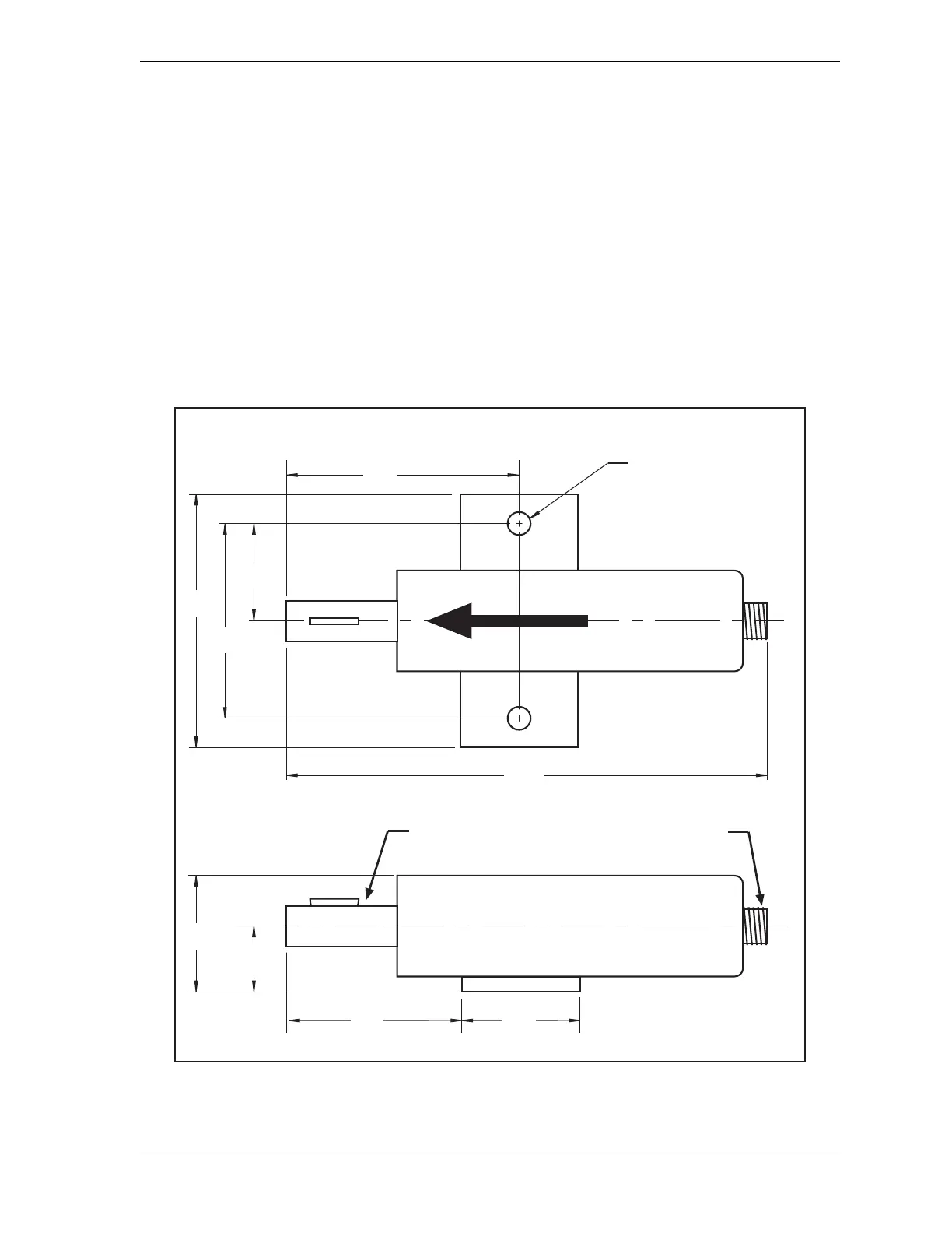
Figure 2-11. Resolver: Mounting Dimensions
2.75
(69.9)
1.06
(26.9)
1.75
(44.5)
2.00
(50.8)
3/4 dia. shaft (19.05)
standard key
Electrical connector
for cable
3.62
(91.9)
0.34 (8.6) dia holes
2 places
9.16
(232.7)
RESOLVER IS AT ZERO WHEN
KEYWAY IS ALIGNED WITH ARROW
3.00
(76.2)
3.75
(95.3)
1.50
(38.1)
Resolver shown in
zero-degrees position,
with key perpendicular
to base
Dimensions: inches
(mm)