WPC 2000 User Manual 1128500
Installation 2-27
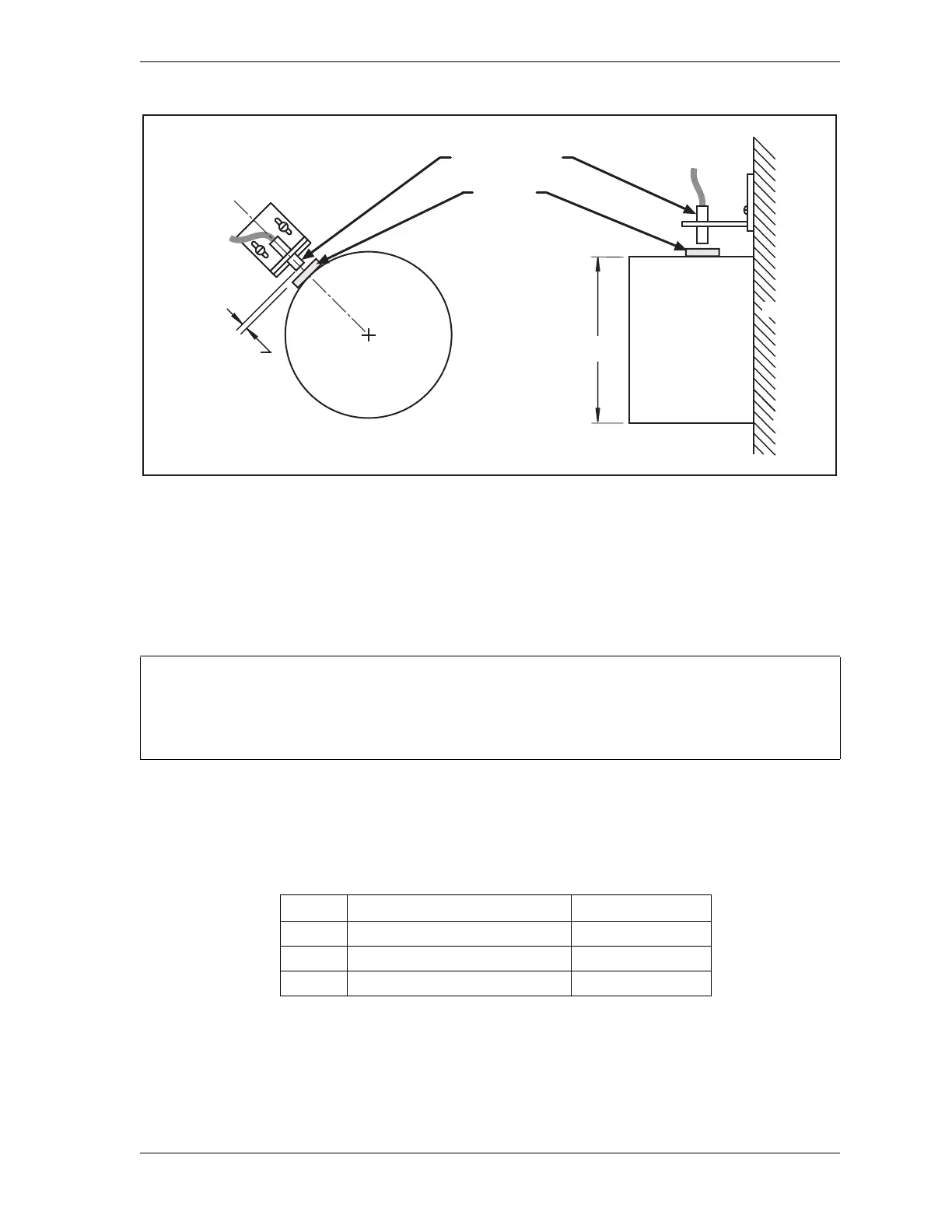
Place the magnet temporarily on the crankshaft or other mounting surface while you set the
gap between the switch face and the magnet. After tightening down the bracket’s mounting
screws, remove the magnet and put it in a safe place until you mount it permanently.
Wiring the Overrun Sensor Switch
Run the cable for the magnetic switch through conduit to the WPC 2000. Connect the wires to
terminal blocks on the WPC 2000 Main Processor board, as shown in Table 2-2 and Figure 2
at the end of the manual.
Figure 2-15. Overrun Sensor Magnetic Switch: Installation Example
You can run both the resolver wires and the overrun limit sensor cable through the same conduit.
If you do so, wait to cut the cable and wires until both the resolver and the overrun limit sensor are
installed.
Table 2-2. Overrun Sensor Switch Wiring Connections
Pin # Signal Wire Color
23 +24 Vdc Red
24 Overrun input to WPC 2000 White
25 Ground Black
Crankshaft
Gap between
magnet and
magnetic switch
1/8 to 3/16
Crankshaft
Press
Magnetic switch
Magnet
Mount temporarily
with tape.
Hard mount later.
Diameter
4-6