WPC 2000 User Manual 1128500
Installation 2-55
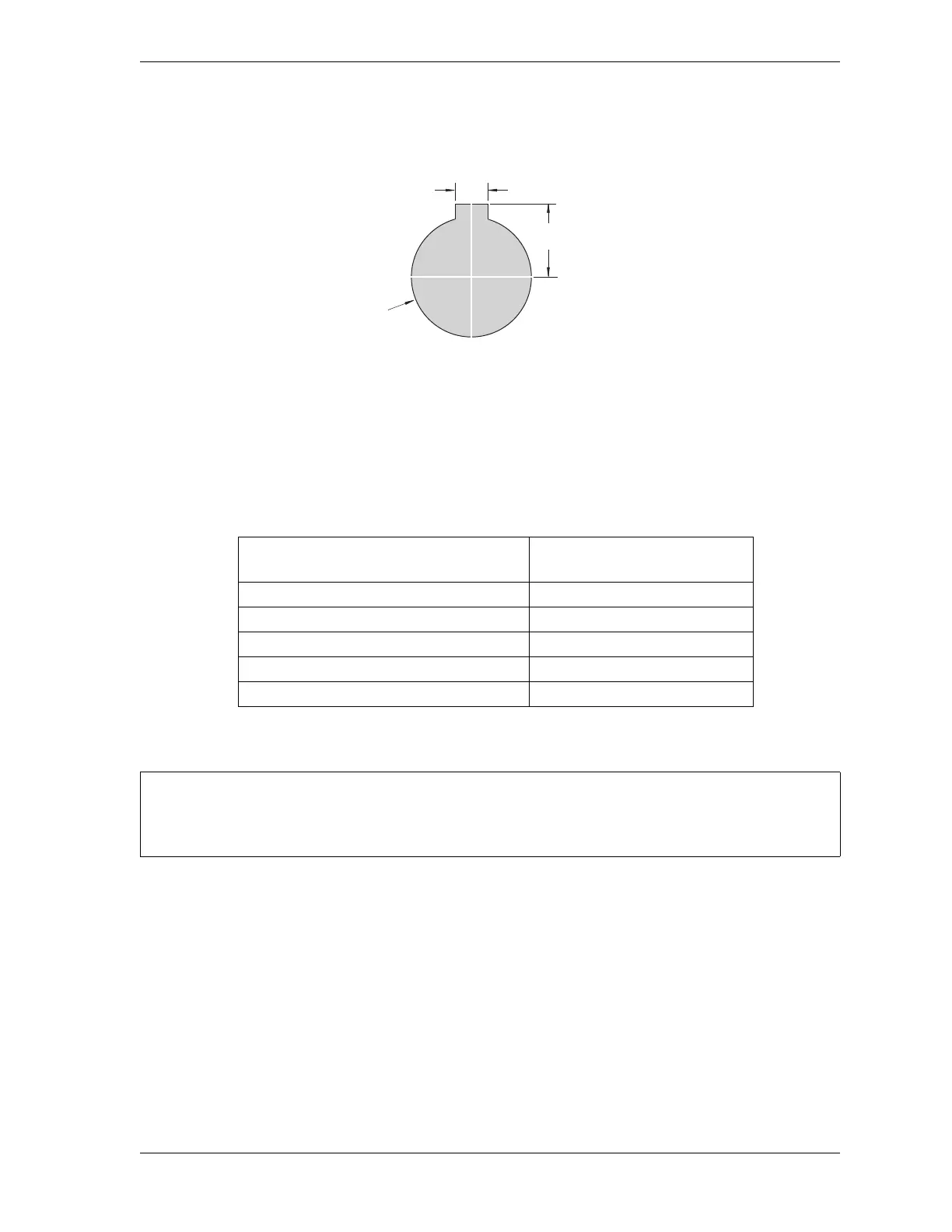
2. Cut holes in your enclosure or console for the selector switches, referring to Figure 2-29
for cutout dimensions. Dimensions are the same for all switches.
3. Install the selector switches.
4. Wire each selector switch to the appropriate terminal block on the WPC 2000 Display
board, referring to Table 2-16 and Figure 5 at the back of the manual for wiring
connections
Installing Display Board Kit with Selector Switches
1. Make sure that your display board kit contains the following components:
• Label
• PC board
• Push button
• Mute lamp
• Key switch with wiring harness assembly
• Four standoffs
• Four lock nuts.
Figure 2-29. Selector Switch: Cutout Dimensions
Table 2-16. Selector Switch Wiring Connections
Selector Switch
Terminal Block on
WPC 2000 Display Board
Stroke Select TB701
Mode Select TB702
Automatic Single-stroke (External Trip) TB703
Operator Station Select TB704
Micro Inch TB705
Install the panel mount display at a height convenient for all users. Experiment to determine a
good height for every user before mounting the display.
0.172
(4.37)
0.672
(17.1)
1.218 dia.
(30.9)
Dimensions:
inches (mm)