WPC 2000 User Manual 1128500
Option 1 User Inputs C-7
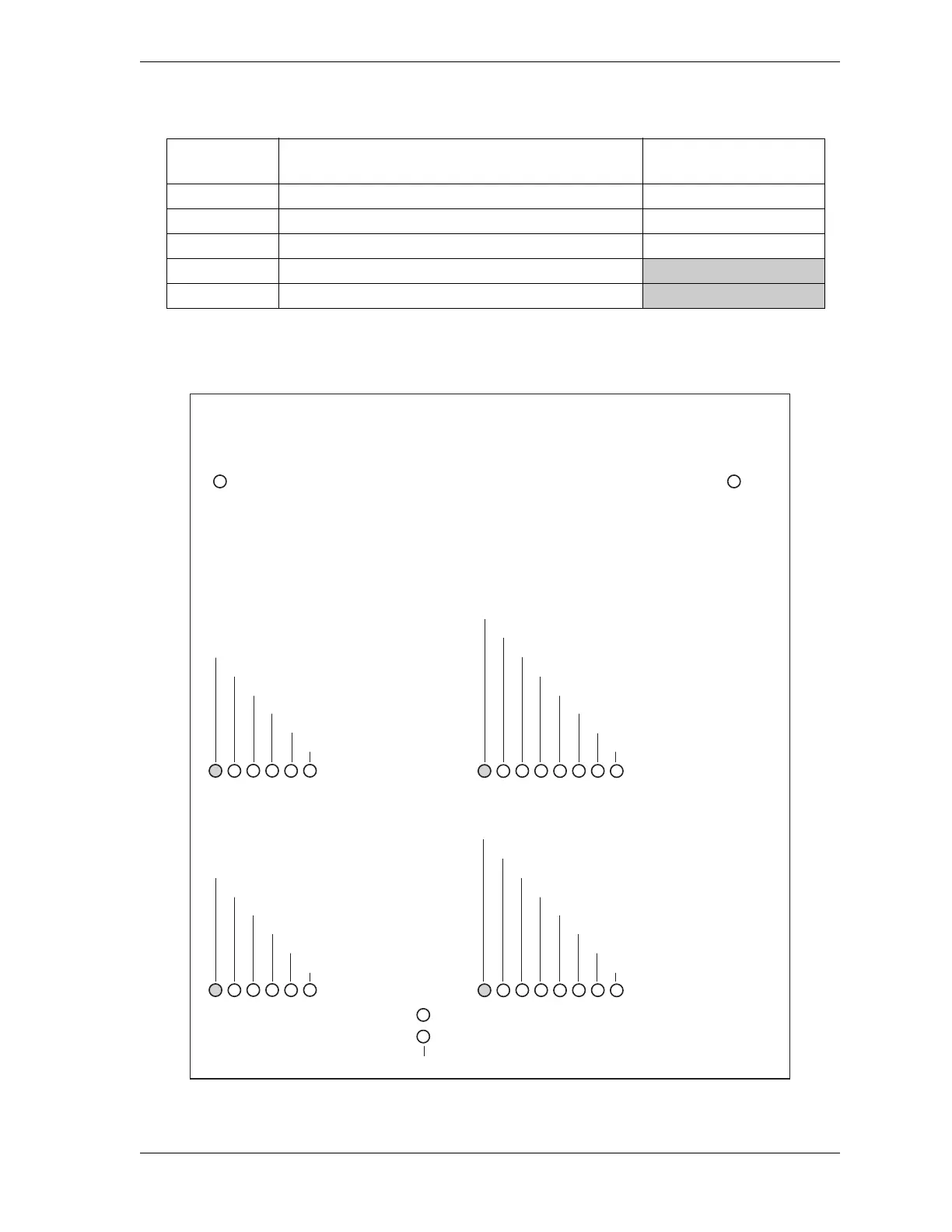
When you have finished wiring user inputs, check the LEDs for the appropriate pin numbers
to make sure that your connections are good (see Figure C-3, below).
460 User input 31 + +24 Vdc
461 User input 37 + (cross-checked with user input 36) +24 Vdc
462 User input 39 + (cross-checked with user input 38) +24 Vdc
463 Ground
464 Ground
Figure C-3. WPC 2000 Option 1 Board: LED Map
Table C-3. WPC 2000 Option 1 Board: Wiring Connections, TB602 (Cont.)
Pin # User Input
Terminal for Jumper
Bypass Connection
GROUP 9
436 - User input 15 -
431 - User input 32 + (x-ch. w/33)
432 - User input 34 + (x-ch. w/35)
433 - User input 12 -
434 - User input 13 -
435 - User input 14 -
GROUP 8
453 - User input 38 + (x-ch. w/39)
448 - User input 22 +
449 - User input 23 +
450 - User input 24 +
451 - User input 25 +
452 - User input 36 + (x-ch. w/37)
GROUP 11
445 - User input 21 -
438 - User input 33 + (x-ch. w/32)
439 - User input 35 + (x-ch. w/34)
440 - User input 16 -
441 - User input 17 -
442 - User input 18 -
443 - User input 19 -
444 - User input 20 -
GROUP 10
462 - User input 39 + (x-ch. w/38)
455 - User input 26 +
456 - User input 27 +
457 - User input 28 +
458 - User input 29 +
459 - User input 30 +
460 - User input 31 +
461 - User input 37+ (x-ch. w/36)
+ 5 VDC A
+ 5 VDC B
Serial port Receive and Transmit LEDs on Main Processor board (visible through holes in Option 1 board)
Shaded LEDs are green; all others are red. LEDs in each group are identified by number.
Corresponding pin numbers for each LED are also shown.
63
2
4
1
5
6
5
3
2
8
4
7
1
63
2
4
1
5
6
5
3
2
8
4
7
1
 Loading...
