Pre-Installation
Greenstar 2000 – 6 721 820 552 (2021/02)
14
4.1.4 System fill
Integral filling link
• An optional filling link accessory is available to fill the system.
– Refer to filling link instructions for fitting and operation.
Filling primary sealed systems
NOTICE
Filling the primary sealed system
The system must not be filled with salt based softened water.
▶ Ensure the primary water filling point uses an untreated cold water
connection from the mains supply, before a water softener.
• Filling the system must comply with one of the following methods
shown.
• The filling point must be at low level and must never be a permanent
connection to the mains water supply.
• Filling loops must be WRAS approved.
• If the external filling link is sited away from the appliance, then a
pressure gauge should be installed at the filling point.
The pressure shown on the gauge may differ from that shown on the
digital display. Final system pressure adjustments must be made whilst
referencing the digital display.
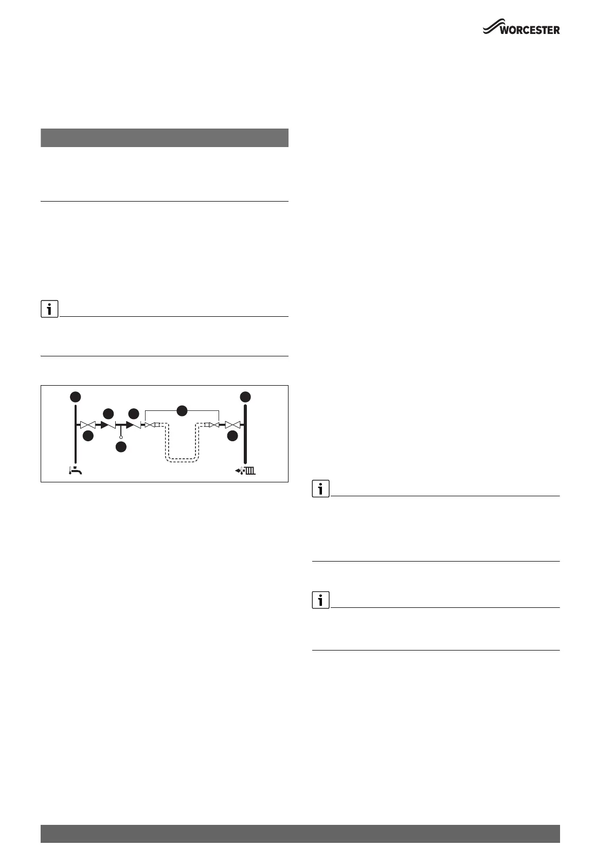
External filling loop
Fig. 8 External filling loop system fill example
[1] Cold mains inlet pipe
[2] Stop valve
[3] Check valve
[4] Test point
[5] Hose union
[6] Central heating flow pipe
4.2 Mains supply
4.2.1 Electrical supply
• Supply: 230V AC - 50 Hz
• This appliance must not be connected to a three phase supply.
• The wiring between the appliance and the electrical supply must
comply with the latest IET wiring regulations that apply to wiring a
fixed appliance for Class 1 equipment.
• The correct type of RCD must be employed where additional
protection is required that is suitable for a low energy DC modulating
pump according to IET wiring regulations.
• External 3 A fuse to BS1362.
• The appliance must be earthed.
• Cable: PVC insulated 0.75mm
2
(24 x 0.2mm) temperature rated to
90 °C, to BS EN50525.
• Any additional components that are connected to the appliance with
mains electrical supply must not have a separate supply.
• Additional equipment wired to the appliance must comply with the
latest IET wiring regulations.
• Appliance protection rating - IPX4D
4.2.2 Gas supply
• Appliances using Natural Gas (NG) must be connected to a governed
meter.
• Appliances using Liquid Petroleum Gas (LPG) must be connected to
a regulator.
• Installation and connection of the gas supply to the appliance must
be in accordance with the latest version of BS6891.
• Gas pipe sizing should be calculated to ensure no more than the
permitted mbar drop between the meter to the appliance inlet. (
chapter 6).
• The meter and pipe work to the meter must be checked, preferably by
the gas supplier. This is to ensure that the equipment is in good
working order and can meet the gas flow and pressure requirements,
in addition to the demand from any other appliance being served.
Pipe sizing (NG & LPG)
Gas pipe work:
▶ Gas installation pipe work must be designed to ensure the pressure
loss between the meter outlet (NG) or storage and regulator (LPG)
and the inlet to each appliance does not exceed 1mbar (NG) or
2.5mbar (LPG) table 24 ”Allowed mbar pressure drop”.
Basic pipe sizing calculation
Basic pipe sizing calculation.
▶ This method is only a guide - for more complex design please
refer to latest version of BS6891 and training given in ACS.
 Loading...


