Pre-Installation
19
Greenstar 2000 – 6 721 820 552 (2021/02)
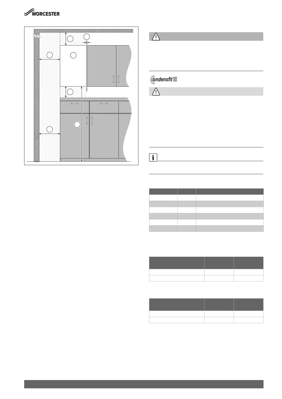
Fig. 13 Reduced front maintenance clearances - Front view
[A] Appliance.
[1] Above appliance - Same clearance required as for standard
clearances of 60/100 flue or 80/125mm flue.
[3] Bottom of appliance to the floor - 1,000 - 1,500mm.
[4] Below appliance - 200mm
[5] One side of appliance - Minimum 300mm.
[6] One side of appliance - Minimum 5mm.
Appliances in compartments
Follow the latest requirements of BS6798 and BS5440 and note:
• Minimum clearances must be maintained.
• An access door is required to install, service and maintain the
appliance and any ancillary equipment.
• If the appliance is installed in an unventilated airing/storage
cupboard, there is no requirement to make a partition between the
appliance and the storage space as long as the minimum clearances
around the appliance are maintained.
4.4 Flue systems considerations
WARNING
Flue systems
Possible flue gas escape
▶ Use Worcester, Bosch Group approved Condensfit II flue systems
only, no other manufacturer’s flue have been tested or approved for
use with Worcester, Bosch Group appliances.
CAUTION
Concealed flue systems:
▶ Where a flue system is going to be concealed, provision must be
made for service and inspection.
▶ Voids containing concealed flues must have at least one inspection
hatch no less than 300mm square.
▶ Flue joints within the void must not be more than 1.5 metres from the
edge of the inspection hatch.
▶ Inspection hatches should be located at changes of direction.
▶ If this is not possible, bends should be viewable from both directions.
Refer to the manual supplied with the Worcester, Bosch Group flue kit for
complete installation instructions.
Flue kit part numbers
Table 13 Flue kit assembly part numbers
4.4.1 Flue length
Horizontal maximum flue lengths
Table 14 Maximum flue lengths - Horizontal flues
Vertical maximum flue lengths
Table 15 Maximum flue lengths - Vertical flues
Part number Flue Ø Description
7 716 191 082 60/100 Telescopic horizontal flue kit
7 716 191 171 60/100 Extended telescopic horizontal flue kit
7 733 600 048 60/100 Horizontal high level telescopic flue kit
7 719 003 702 80/125 Telescopic horizontal flue kit
7 719 002 430 60/100 Vertical balanced flue kit
7 719 002 431 80/125 Vertical balanced flue kit
Flue length [L] Flue length [L]
Appliance 60/100 80/125
GR2300iW 25 C 9,000mm 12,000mm
GR2300iW 30 C 9,000mm 12,000mm
Flue length [L] Flue length [L]
Appliance 60/100 80/125
GR2300iW 25 C 12,000mm 15,000mm
GR2300iW 30 C 12,000mm 15,000mm
 Loading...


