Commissioning
45
Greenstar 2000 – 6 721 820 552 (2021/02)
6.2.1 Filling the appliance and adding Inhibitor
Before pressurising the system.
The appliance integral expansion vessel is pre-charged to 0.75 bar
(equal to a static head of 7.5m (24.6ft)). A Schrader type valve is fitted
to the expansion vessel to allow for pressure adjustment if required.
▶ If an extra expansion vessel is fitted to the central heating system,
ensure that it is set to the same pressure as the appliance internal
expansion vessel, refer to separate instructions supplied with the
extra expansion vessel.
Filling the system - Sealed systems
NOTICE
▶ Salt based softened water must not be used to fill the central heating
system.
▶ Check that the drain cocks and manual air vents are closed and all
radiator valves are open.
▶ Add a suitable inhibitor or combined inhibitor/anti-freeze, if the
system might be exposed to freezing conditions, to the heating
system water in accordance with the manufacturers instructions.
▶ Turn on the water main and open the system valves.
▶ Fill the system to between 1 and 1.5 bar via a WRAS approved filling
loop or one of the filling link accessories.
– Refer to filling link accessory instructions for operation and use.
▶ The Automatic Air Vent will release any air trapped in the appliance.
▶ Manually vent all radiators, tighten the vent screws when completed
▶ Check the system for any leaks and correct if required.
▶ Top up the system pressure if the pressure has dropped below 1 bar.
▶Isolate and remove the filling loop connections to the system.
– Refer to Integrated filling link accessory instructions for any
further actions required after filling the system.
Keyless filling link
▶ An additional 0.75bar static mains pressure is required above
required system pressure to ensure the effective operation of the
keyless filling link accessory.
Adjusting the operating pressure of the heating system
Table 22
If the indicator is below 1 bar when the system is cold:
▶ Top up the water until the indicator is between 1 bar and 1.5 bar
again.
If pressure is not being maintained:
▶ Check tightness of expansion vessel and heating system.
6.3 Circulation pump
The circulating pump must be left in factory default setting (Constant
speed mode - curve III) to ensure hot water performance.
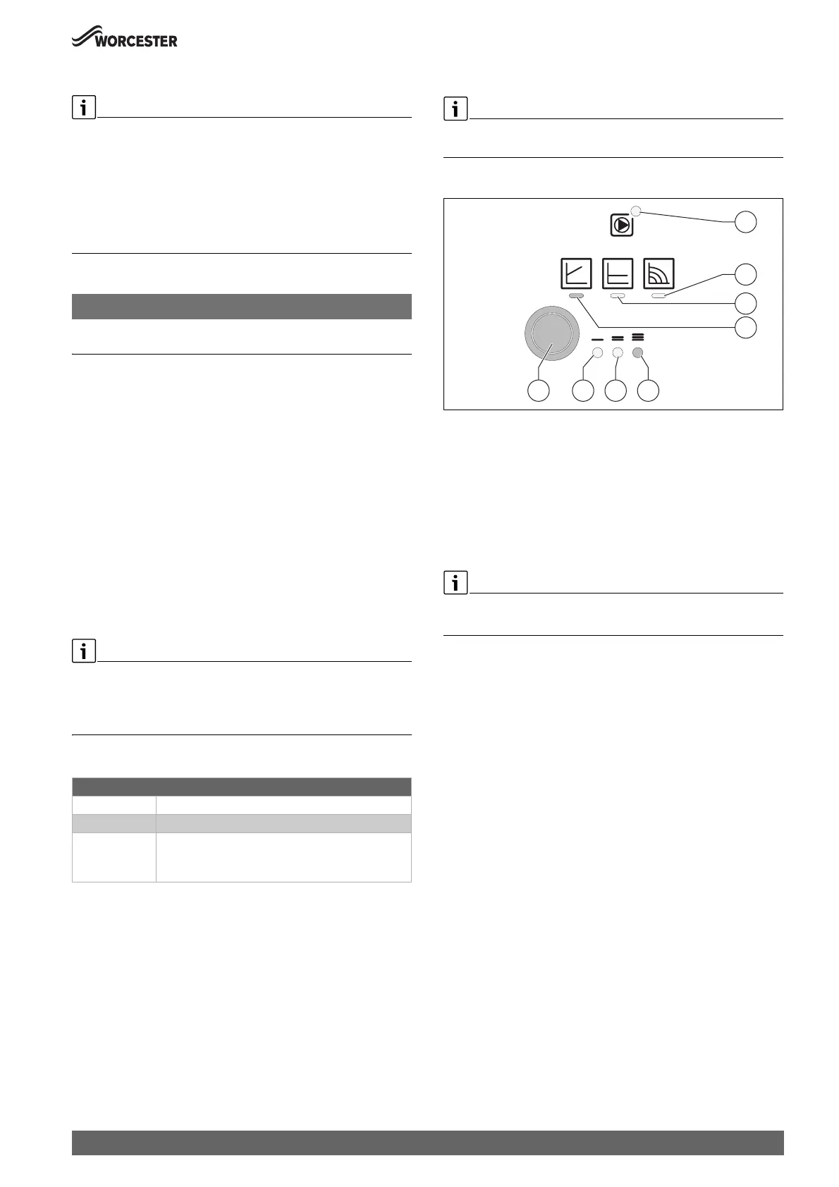
Controller module overview
Fig. 59 Overview
[1] Operation/fault indicator
[2] Constant speed mode indicator
[3] Constant pressure (p-c) mode indicator
[4] Self modulating (p-v) mode indicator
[5] Pump curve 3 selection indicator
[6] Pump curve 2 selection indicator
[7] Pump curve 1 selection indicator
[8] Selection button
Default setting
▶ Constant speed mode - curve III
Selection button
To return to the default factory setting, should there be an instance
where an alternative setting is entered, please follow this advice:
▶Press
– Select constant speed control mode.
– Select pump curve III.
For additional pump functions:
▶ Press and hold to:
– Activate the pump venting function (press for 3 seconds).
– Activate manual restart (press for 5 seconds).
– Lock/unlock button (press for 8 seconds).
Display on the pressure gauge
1 bar Minimum charge pressure (when system is cold)
1 - 1.5 bar Optimal charge pressure
3 bar Maximum charge pressure at maximum heating
water temperature must not be exceeded (pressure
relief valve opens).
0010029670-001
1
2
4
3
8 7 6 5
 Loading...


