Pre-Installation
Greenstar 2000 – 6 721 820 552 (2021/02)
22
4.4.3 Plume management system
NOTICE
Plume management terminal:
▶ The plume management terminal must not be sited within 500mm of
the air intake, and must not exceed the maximum straight length for a
horizontal Ø 60/100mm flue with a 60mm plume management
system.
Horizontal plume management runs
▶ The initial horizontal run from the terminal elbow must have a
minimum 10° fall back, (stop tabs in the elbow prevent less than 10°)
to the appliance for proper disposal of condensate.
▶ Any further horizontal runs after an elbow can be 3°.
WARNING
Minimum plume management length:
The minimum distance of 500mm must be maintained between air inlet
and exhaust.
▶ Do not terminate the plume management inside the terminal
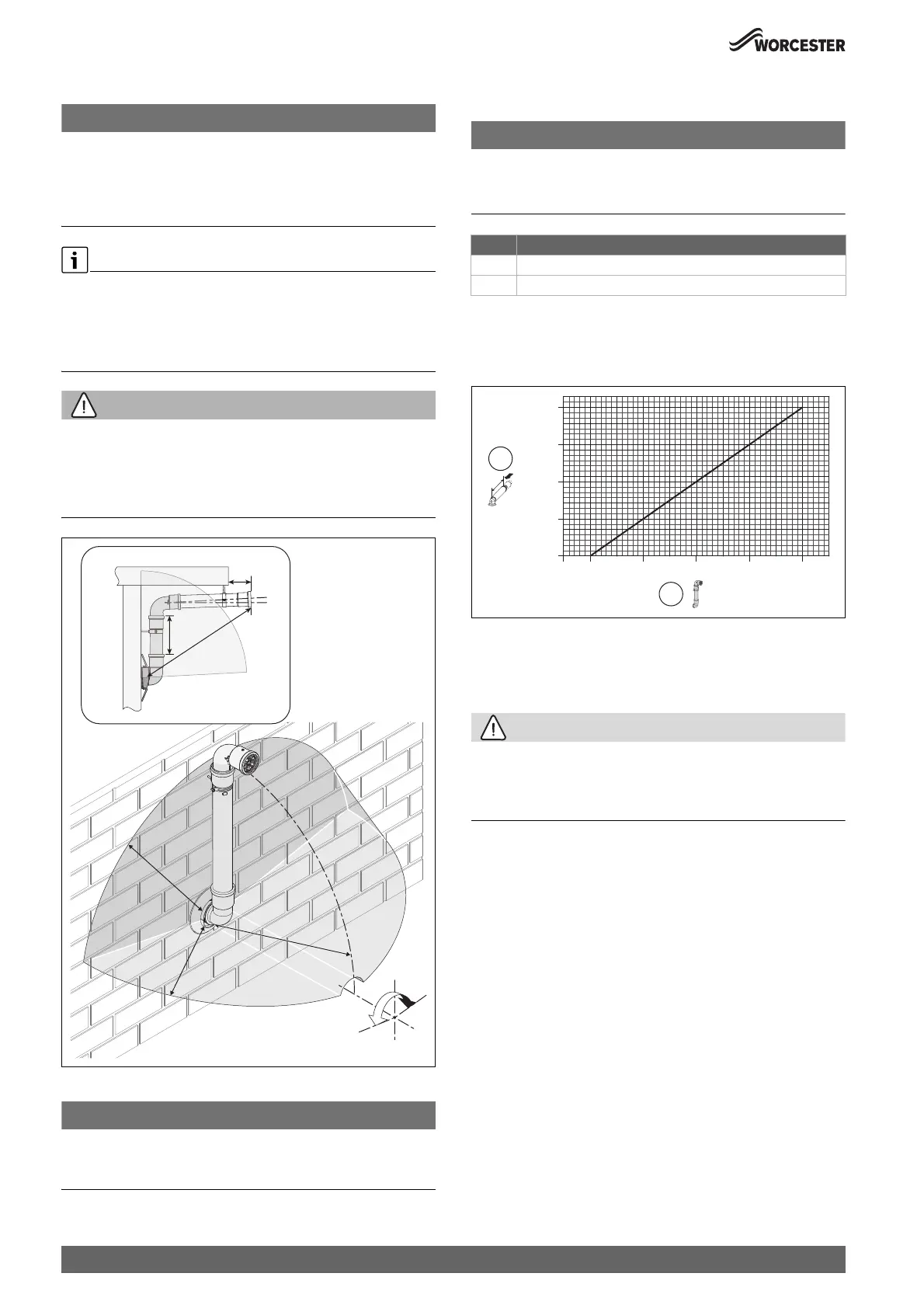
exclusion zone (shaded area) shown in figure 26.
Fig. 26 Terminal exclusion zone
NOTICE
Cutting the 500mm pipe
▶ The Plume management extension kit contains the components
required for such a configuration.
Plume management bends
NOTICE
Effective plume management lengths of bends:
Each bend used has an equivalent straight plume management length.
▶ Refer to the table 17.
Table 17 Effective length of bends
For every extra 1,000mm of plume management after the first 500mm,
the internal 60/100 flue length must be reduced by 700mm, up to a
maximum of 4,500mm of plume management.
Fig. 27 Reduction to flue length as plume length increases graph
[1] Reduction to flue length [mm] (maximum reduction 2,800mm)
[2] Plume length [mm] (maximum plume length 4,500mm)
4.4.4 Flue terminal positions
CAUTION
Flue terminal positions
▶ All measurements are the minimum clearances required.
▶ Terminals must be positioned so to avoid combustion products
entering the building.
0010013548-003
±80°
5
00
m
m
5
00
mm
5
0
0
m
m
100mm
3°
≥140mm
X
≥
5
00
m
m
Bend Effective plume managnement length
45° 0.75 metres
90° 1.5 metres
0010023114-001
0
700
1,400
2,100
2,800
500 1,500 2,500 3,500 4,500
[mm]
[mm]
2
1
 Loading...


