Pre-Installation
13
Greenstar 2000 – 6 721 820 552 (2021/02)
Checking the size of the expansion vessel
To determine whether an additional expansion vessel is required: Follow
the steps below:
▶ Calculate the total system volume (litres).
– Plot a line vertically on the chart ( Fig. 5).
▶ Determine the central heating maximum operating flow temperature.
– Plot a line horizontally on the chart ( Fig. 5).
▶ Determine the pre-charge in the expansion vessel based on static
head, 1 metre = 0.1 bar.
– Static head should be measured between the expansion vessel
and the highest point on the system (top of the highest radiator).
▶ Select a curve from the key below (1-5).
▶ System pressure should be set at 0.1 - 0.25 bar higher than the
vessel pre-charge.
– It must be at least to the minimum on appliances with an analogue
gauge.
– Minimum pressure settings may need to be adjusted to suit on,
appliances with a digital gauge, in the applicable menu function.
– Intelligent filling settings may need to be adjusted to suit on,
appliances with the automatic filling accessory, in the applicable
menu function.
If the dissected lines are in area A then no additional expansion is
required.
If the dissected line is in are B then an additional expansion vessel must
be installed ( Fig. 4).
Fig. 5 Curves for the expansion vessel
1 Pre-charge pressure 0.5 bar (minimum)
2 Pre-charge pressure 0.75 bar
3 Pre-charge pressure 1.0 bar
4 Pre-charge pressure 1.2 bar
5 Pre-charge pressure 1.3 bar
A Operational capacity of the expansion vessel (left of the relevant
curve)
B Additional expansion vessel required (right of the relevant curve)
T Maximum operating temperature [ °C]
V Total System Volume [l]
The default pre-charge pressure for the expansion vessel is 0.75 bar
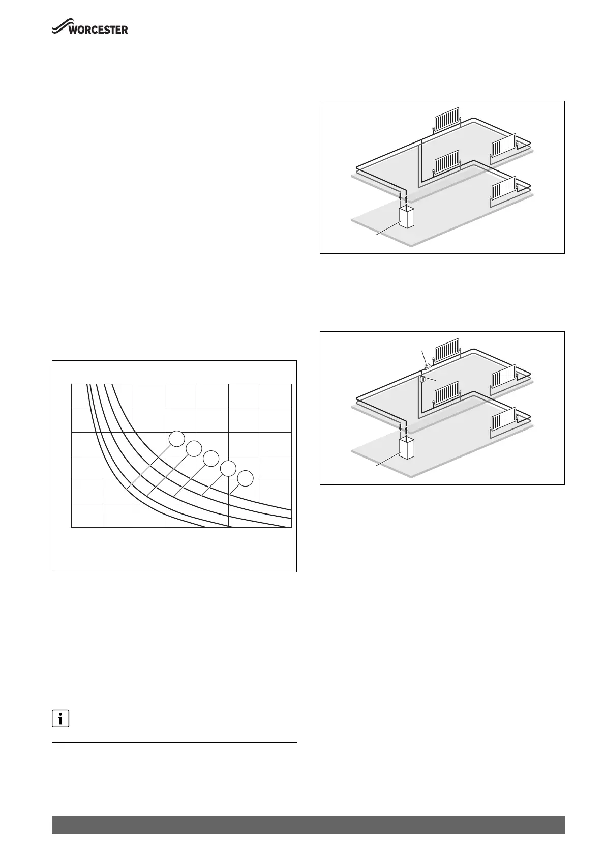
4.1.3 System layouts examples
Sealed primary system - Single central heating circuit:
Typical primary system example
Fig. 6 Single central heating circuit example
[1] Appliance
Sealed primary system - 2 x central heating zones:
• Requirement for new builds if the floor area of a property is over
150m
2
.
Fig. 7 Separated heating zones
[1] Appliance
[2] Zone valves
0010016558-002
A
B
4
5
3
2
1
30
40
50
60
70
80
90
0 100 200 300 400 500 600 700
T[°C]
V[l]
1
0010021227-002
 Loading...


