Installation
Greenstar 2000 – 6 721 820 552 (2021/02)
38
5.3 Hanging the appliance
NOTICE
Transport protection covers
▶ Remove any internal transport packaging and protection covers from
the appliance where applicable.
NOTICE
Risk of damage to casing!
The front cover may be damaged whilst mounting the appliance on the
wall.
▶ Remove front cover prior to hanging.
Installing pipework
DANGER
Contaminated heating water can damage the appliance!
Residue in the pipe work can damage the appliance.
▶ Flush the pipe work before installing the appliance.
▶ Determine internal diameter for the gas supply.
▶ All pipe connections in the heating system must be able to withstand
a pressure of 3 bar, and 10 bar in the DHW circuit.
▶ Install service valves and gas isolator.
▶ To fill and drain the heating system, install a drain valve at the lowest
point of the system.
▶ Install the Pressure Relief Valve discharge pipe to the latest advice in
BS6798.
▶ Always route discharge pipes with a continuous fall.
Appliance connections
NOTICE
Commissioning without water damages the appliance!
▶ Only operate the appliance when filled with water.
▶ OPTIONAL: Fit the supplied copper CH tails [1]to the CH flow and
return 22mm compression connections.
– These tails are designed to allow all hydraulic and gas connections
to be 30mm from the wall.
Fig. 43 CH pipe tails fitting
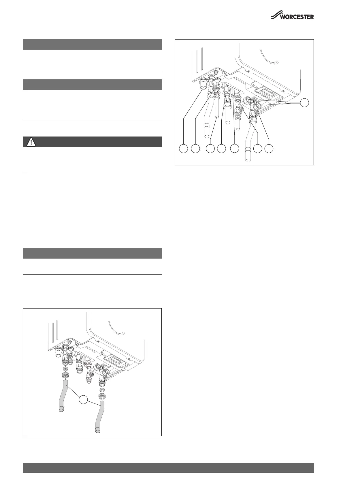
Fig. 44 Connections on the gas and water side
[1] Condensate hose connection
[2] CH flow valve
[3] DHW outlet connection
[4] PRV tail connection (heating circuit)
[5] Gas isolator
[6] Cold Mains inlet valve
[7] CH return valve
[8] Connections for keyless filling link accessory
▶ Connect the CH flow pipe to the copper tail, if used.
▶ Connect the CH return pipe to the copper tail, if used.
▶Connect the gas supply to the appliance gas cock 22mm
compression connection.
▶ Connect the Cold Mains inlet to the appliance 15mm compression
connection.
▶ Connect the DHW outlet to the appliance 15mm compression
connection.
0010033721-001
1
 Loading...


