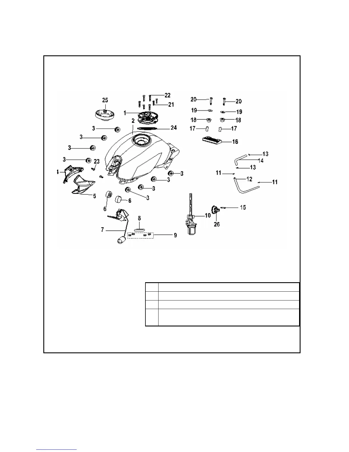
Fuel Tank Assembly
A
Max. capacity of fuel tank:16L
B
Tightening torque of Bolt 13 in the diagram:5-9 N·m
D
Tightening torque of Bolt 15 in the diagram:5-9 N·m
E
Note:Fuel switch shall be set at “OFF” position while removing fuel
tank.
1 Fuel tank lock 2 Fuel tank block assembly 3 Protecting plate rubber gasket 4 Right fuel tank protecting
plate 5 Left fuel tank protecting plate 6 Fuel tank installation gasket 7 Fuel sensor assembly 8 Sensor rubber
gasket 9 Nut M6 10 Fuel switch assembly 11 Wire clamp 8 12 Oil hose φ4.5×2×140 13 Wire clamp 9
14 Oil hose φ7×11×500 15 Screw M4×25 16 Fuel tank installation gasket 17 Fuel tank installation shaft sleeve
18 Rubber boot 19 Fuel tank installation washer 20 Bolt M6×35 21 Hexagon socket screw M5×30 22
Hexagon socket screw M5×14 23 Mounting screw for fuel tank protecting plate 24 Fuel cap seal ring 25
Fuel tank support assembly 26 Switch handle

 Loading...