Connecting method: positive (+) to blue/white, negative (-) to green/white.
Min. voltage: higher than 1.7V.
* Attention
Please do not touch the metal parts of testing probe with your
fingers while measuring the voltage, or you will be shocked.
Please take care.
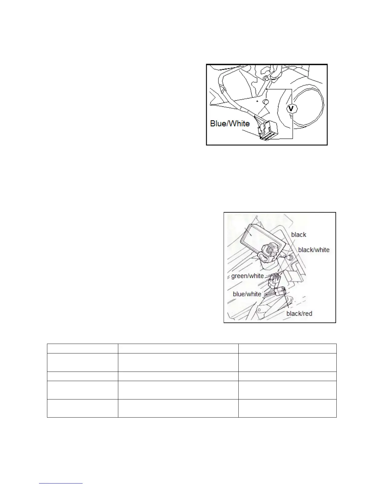
When the peak voltage measured at connector of CDI
assembly is abnormal, take down the protecting plate on the
right side of vehicle and remove connector of magneto.
Trigger (blue/white) is connected with a shunt.
• When the measured voltage at CDI assembly terminal is abnormal, but measured voltage at magneto terminal is
normal, it indicates that the connector is of poor contact or wiring is broken.
• When measured results at both sides are abnormal, the trigger is damaged. Please refer to items listed in Diagnosis
Table and check.
2.4 CDI Assembly
2.4.1 System Inspection
System inspection
Remove CDI assembly and check components related to the ignition
system at wiring terminal.
2.4.2 Inspection
Remove CDI assembly and check if connectors are loosen or
corrosive.
Item Measuring terminal Standard Value(20)
Main switch Red—Red/White On continuity when main switch is
“OFF”.
Trigger
Blue/White-White/Green
100-200Ω
Primary coil of ignition
coil
Black/White—Black 0.4Ω±10%
Secondary coil of ignition
coil
Black—spark plug cap(not including spark
plug)
3-5.5KΩ±10%

 Loading...