C-5000 COMMUNICATION MANAGEMENT CONTROLLER
INSTALLATION MANUAL
Publication No. 150-041118 Page 4-1
Rev A Section 4 –Electrical Installation
Sep 2001
SECTION 4 - ELECTRICAL INSTALLATION
1. General
The following section describes the wiring requirements and options for the installation of the
system. Because the system has so many features and options, it is recommended that the
installer take the time to read pin descriptions and all notes on wiring diagrams before designing
an installation.
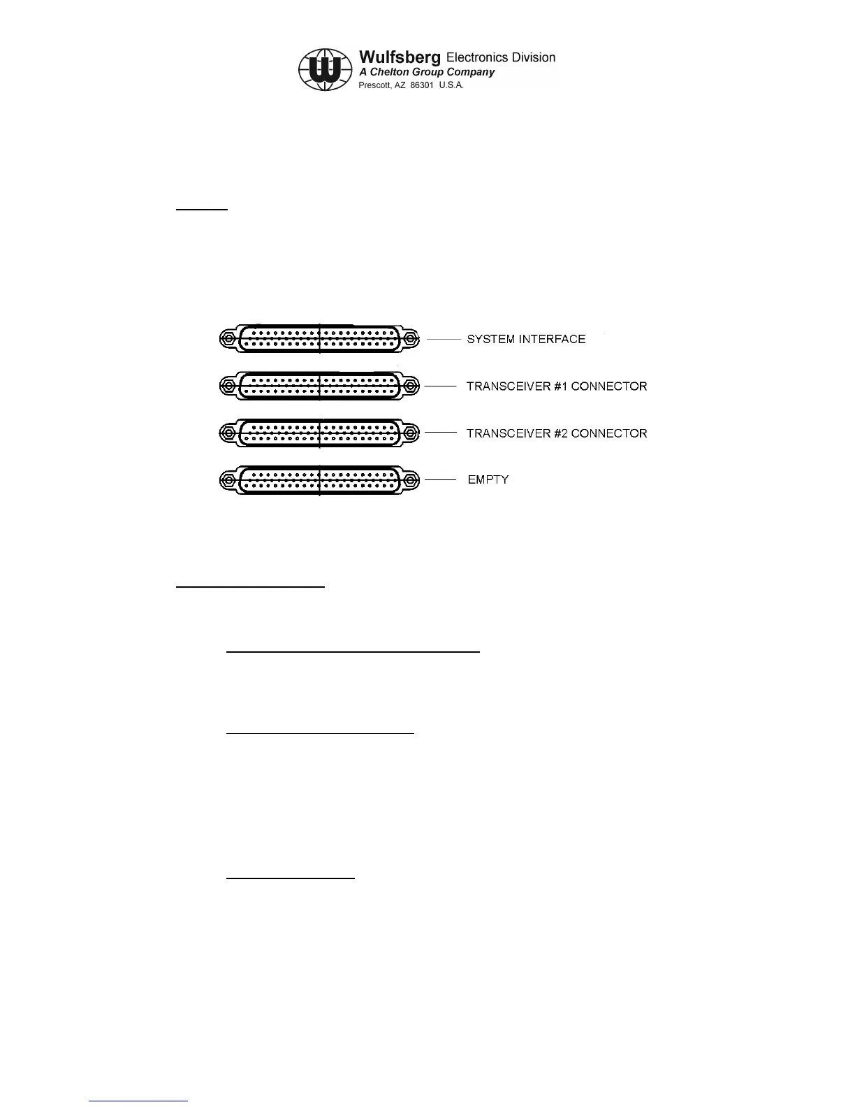
Figure 4-1 Rear View of C-5000
2. Wiring Considerations
To simplify the systems design, follow the steps below:
Step 1: Determine the type and number of radios. The C-5000 can control one or two
transceiver systems. The word system is used because a Flexcomm I installation can be
made of multiple transceivers electrically daisy chained to make one system. Based on the
type of radio, chose the part number of C-5000 that applies to your application.
Step 2: Determine the type of antenna. For each transceiver, determine the appropriate
antenna. For Flexcomm I transceivers, see the proper installation manuals for options. For
the RT-5000, the process begins by determining if the user needs optimum 30-88MHz
performance. If so, the recommended antenna system will be an “active” antenna (i.e. one
that is electrically tuned for maximum performance). If the user rarely uses 30-88 MHz, then
passive antenna is suggested. Passive antennas are less expensive and less complex to
install. Remember that performance in the 30-88 MHz frequency range is very degraded vs.
an active antenna.
Step 3: Microphone/Headset. If only one radio is installed, use the primary mic/headset
port. If two radios are installed, use primary mic/headset for transceiver system #1 and
secondary mic/headset for transceiver system #2. If only one mic/headset port is available
on the audio panel, use the primary mic/headset port and configure the C-5000 to operate in
“single mic mode”.
 Loading...