C-5000 COMMUNICATION MANAGEMENT CONTROLLER
INSTALLATION MANUAL
Page 4-2 Publication No. 150-041118
Section 4 – Electrical Installation Rev A
Sep 2001
Step 4: Panel Lighting. Select the input pin on P500 for the desired backlighting.
Options are 28 Vdc (pin 30) or 5 Vdc/5vrms (pin 8).
Step 5: System Wiring. Based on steps 1-5, choose the wiring diagrams from this
section that apply to your configuration. Note that if you have two RT-5000’s in your system,
copy the wiring illustrated for P501 to P502. In other words, choose the wiring for each radio
and apply it to the appropriate connector.
A. C-5000 System Interface Connector, P500 Wiring Considerations
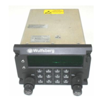
(1) P500 Connector
Figure 4-2 P500 Connector
 Loading...