Do you have a question about the Wulfsberg C-5000 and is the answer not in the manual?
Describes how to use the manual and outlines its sections.
Covers system characteristics, interface capabilities, and power requirements.
Contains system component dimensions, racking, weights, and installation data.
Provides wiring information for installing C-5000 with FLEXCOMM II.
Provides wiring information for installing C-5000 with FLEXCOMM I.
Contains system configuration and preset channel programming procedures.
Provides checkout procedures for the system after installation.
Lists components for C-5000 and FLEXCOMM II, including transceivers and antennas.
Lists FLEXCOMM I transceivers and antennas, with references to installation manuals.
Explains C-5000 part number configuration and notes on frequency agile units.
Lists various RT-5000 transceiver part numbers and their descriptions, including encryption.
Lists FLEXCOMM II antenna part numbers, descriptions, and associated logic converters.
Lists RT-30 transceiver part numbers and their frequency ranges and features.
Lists RT-118 transceiver part numbers and their frequency ranges and bandwidths.
Lists RT-138 transceiver part numbers, frequency ranges, and features like Guard Receiver.
Lists RT-138F transceiver part numbers, frequency ranges, and encryption compatibility.
Lists RT-406F transceiver part numbers, frequency ranges, and encryption compatibility.
Lists RT-450 transceiver part numbers, frequency ranges, and features like Guard Receiver.
Lists RT-7200 transceiver part numbers, frequency ranges, and features like Guard Receiver.
Lists RT-9600 transceiver part numbers, frequency ranges, and features like Guard Receiver.
Lists RT-9600F transceiver part numbers, frequency ranges, and encryption compatibility.
Describes system specifications, interface information, and typical system configurations.
Illustrates examples of how to configure aircraft installations with C-5000 and RT-5000.
Details power requirements for C-5000, FLEXCOMM II (RT-5000), and FLEXCOMM I transceivers.
Specifies C-5000 controller features like number of channels, temperature, and lighting.
Details RT-5000 transceiver specifications including tunability, modes, frequency bands, and TX power.
Lists specifications for RT-5000 antennas, including frequency, VSWR, gain, and temperature.
Lists specifications for the AT-560 antenna, including frequency, VSWR, gain, and temperature.
Lists specifications for the AT-160 antenna, including frequency, VSWR, gain, and temperature.
Lists specifications for the AT-5000 antenna, including frequency, VSWR, gain, and temperature.
Lists specifications for the AT-550 antenna, including frequency, VSWR, gain, and temperature.
Lists specifications for the AT-50 antenna, including frequency, VSWR, gain, and temperature.
Lists specifications for the AT-51 antenna, including frequency, VSWR, gain, and temperature.
Lists specifications for the AT-140 antenna, including frequency, VSWR, gain, and temperature.
Lists specifications for the AT-400 antenna, including frequency, VSWR, RF power, and efficiency.
Refers to FLEXCOMM I Installation Manual for specification data on transceivers and antennas.
Provides instructions and considerations for the proper mechanical installation of C-5000 systems.
Outlines the procedure for unpacking and visually inspecting all equipment for damage.
Lists component weights for C-5000, RT-5000, antennas, and FLEXCOMM I components.
Provides part numbers and supplier information for contacts, crimp tools, and tools.
Provides part numbers and supplier information for contacts, crimp tools, and insertion/removal tools.
Instructions for mounting the C-5000 unit using Dzus/rails per MIL MS-25213.
Details mounting the RT-5000 for cooling, including clearance and connector attachment.
Provides general instructions for mounting various antennas.
Instructions for mounting AT-560 and AT-5000 antennas, including screw requirements.
Note that FC-5000 Logic Converter is required for AT-560 and AT-5000 antennas.
Instructions for mounting AT-160 and AT-150 antennas, including screw requirements.
Instructions for mounting AT-550 antenna, including screw requirements.
Note that FC-550 Logic Converter is required for the AT-550 antenna.
Instructions for mounting AT-50 and AT-51 antennas, considering drainage and sealing.
Note that FC-50 Logic Converter is required for the AT-50 and AT-51 antennas.
Instructions for mounting the AT-400 antenna, including screw requirements.
Instructions for mounting the AT-140 antenna, including screw requirements.
Describes wiring requirements and options for system installation, advising to read pin descriptions.
Provides steps to simplify system design and wiring, including radio type, antenna, and mic/headset.
Details wiring considerations for the C-5000 System Interface Connector P500.
Diagram showing the P500 connector, which is the C-5000 System Interface Connector.
Lists pin names and signals for the System Interface Connector P500.
Details primary carbon mic input impedance, bias, and modulation adjustment range.
Details 27.5 Vdc power and ground connections to the C-5000, including current requirements.
Details wiring considerations for the RT-5000 transceiver.
Diagram showing the J101 connector for the RT-5000 transceiver.
Lists pin names and signals for the RT-5000 Transceiver Connector J101.
Details wiring considerations for the C-5000 Transceiver (FLEXCOMM I) connectors.
Diagram showing the P501/P502 connectors for the C-5000 Transceiver (FLEXCOMM I).
Lists pin names and signals for the C-5000 Transceiver (FLEXCOMM I) Connector P501 or P502.
Details wiring for FLEXCOMM I transceivers like RT-30, RT-118, RT-138, RT-138F, RT-406F, and RT-450.
Explains channeling lines using BCD logic to control transceiver frequency.
Pin that activates CTCSS for transmit tone encode or receiver tone decode.
Lists connectors used for C-5000 components and their Wulfsberg/equivalent part numbers.
Overview of the C-5000 Communication Management Controller and its capabilities.
Lists powerful features of the C-5000, including transceiver control and multi-radio modes.
Summarizes supported Wulfsberg FLITECOMM, FLEXCOMM I, and FLEXCOMM II transceivers.
Details FLEXCOMM II transceivers (RT-5000), frequency range, and Guard Receiver options.
Details FLEXCOMM I transceivers (RT-30, RT-138F, RT-406F), frequency ranges, and Guard Receiver.
Details FLITECOMM transceivers (RT-7200, RT-9600, RT-9600F) and Guard Receiver options.
Checklist to help installers and users set up the C-5000 and RT-5000.
Provides an overview of basic operation for the C-5000.
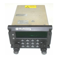
Describes the C-5000 front panel controls, including display, keys, knobs, and ports.
Describes the functions of the C-5000's 12-button keypad for various operations.
Describes the HOME PAGE, the primary operational page showing radio status and information.
Details the procedure for turning the C-5000 system on and off.
Explains how to adjust the C-5000's display brightness using the soft keys.
Explains how to adjust the volume level for Radio 1 and Radio 2 using volume knobs.
Describes how to select preset channels using cursor and value knobs.
Describes how to select preset channels by entering their number via the keypad.
Describes how to select a preset channel by its alphanumeric identifier.
Explains how to select the manual channel (channel 0) for tuning non-programmed frequencies.
Explains how the C-5000 supports direct and repeat modes of operation.
Covers receiving and transmitting operations for the C-5000 system.
Describes how the C-5000 monitors radios for reception and indicates activity.
Explains how to transmit on a radio system by selecting source and keying the microphone.
Describes the process of enabling or disabling transceivers in the system.
Describes how to disable or turn off a transceiver using the VALUE knob.
Describes how to enable or turn on a transceiver using the VALUE knob.
Explains how to use the EDIT PAGE to change preset channel properties.
Describes how to temporarily change properties of a preset channel.
Describes how to change properties of a manual channel.
Covers changing PL (CTCSS) and DPL (DCS) tone settings for channels.
Describes how to turn off receive and transmit tones.
Describes how to select a CTCSS tone using the VALUE knob.
Describes how to select a DCS tone using the VALUE knob.
Explains how to change transmit power between high and low settings.
Describes how to change modulation type (AM/FM) for manual channels.
Describes how to change receiver bandwidth options (Narrow, Standard, Wide, Extra Wide).
Provides an overview of advanced system features available on the C-5000.
Explains how to use the C-5000 to patch into the phone system via DTMF or pulse dialing.
Explains how to establish simulcast operation for simultaneous transmission to multiple locations.
Explains how to establish relay operation for cross-band repeater functionality.
Explains how to establish combined relay and simulcast operation.
Explains how to establish repeater operation for airborne repeater functionality.
Details features related to encryption, including turning it on/off and key management.
Describes how to toggle encryption on and off for a selected radio.
Describes how to temporarily change the preset encryption key (KEYMAT).
Describes how to perform an Over The Air Rekey (OTAR) process.
Describes how to erase encryption keys contained in an RT-5000 transceiver.
Describes how to manually load encryption keys into an RT-5000 digital transceiver.
Details the process of programming preset channels for the C-5000 system.
Describes how to program preset channels using the C-5000 front panel.
Describes how to specify the C-5000's configuration from the front panel.
Details configuring the C-5000 to control an RT-5000, including part number and guard receiver setup.
Details configuring the C-5000 to control non-RT-5000 transceivers like RT-30.
Details how to change system configuration and programming passwords.
Describes setting miscellaneous system properties like encryption and side-tones.
Recommends using PC Remote Programmer software for C-5000 configuration.
Describes initiating a configuration download from Remote Programmer into the C-5000.
Describes uploading the C-5000's current configuration into the RP software.
Provides an overview of the RSS software for radio programming.
Preparation steps for using Motorola RSS software to program the RT-5000 ITM.
Describes the main menu and access to other sections of the RSS software.
Describes GET/SAVE/PROGRAM menu actions like reading, saving, and programming data.
Describes selecting and managing archive files for loading into active memory.
Details the CLONE process for copying Archive data into a target ITM codeplug.
Used to save an Archive to the Hard Disk with options for location and name.
Configures switch labels for conventional and trunking features.
Sets critical items for RT-5000 communication with ITM, including encryption setup.
Controls display aspects of the ITM for proper integration.
Section for assigning channel aspects to a personality numbered 1 through 255.
Sample setup for a secure Analog Personality.
Details personality programming for Conventional P25 Personalities.
Sample setup for a secure Digital Repeater Personality.
Submenu for configuration screens for MDC operations.
Controls setup for MDC (Analog) operations, including Primary ID.
Lead menu to configure all aspects of ASTRO operations for the radio.
Settings for ASTRO radio wide operations, including CAI data attempts and packet size.
Configures particulars of ASTRO Digital operations, including Individual ID.
Assigns personalities to specific zones and channels, with critical requirement for Zone 1 Channel 1.
Acronym for "Amplitude Modulation", used in specific frequency ranges.
RT-5000 can invert audio phase for transmit or receive, useful for DPL systems.
Describes amount of frequency a channel uses for signal transmission.
Group of radio characteristics like frequencies, modulation, and power levels.
Acronym for Communication Management Controller; C-5000 is a CMC.
Acronym for "Continuous Coded Squelch System".
Acronym for "Digital Coded Squelch".
Acronym for "Digital Encryption Standard", an encryption algorithm.
Amount of peak change RF signal varies from carrier based on voice amplitude.
Acronym for "Digital Private Line", also known as DCS.
Dual Tone Multiple Frequency used on telephone keypads.
Mode of operation allowing bypass of repeater, talking directly to another radio.
Method to scramble signals so listeners cannot understand transmitted information.
Number required by algorithm to scramble information for transmitting and receiving.
First generation of Flexcomm control heads and transceivers.
Second generation of Flexcomm control heads and transceivers.
Acronym for "Frequency Modulation", signal frequency varied by voice/data amplitude.
Second receiver added to transceiver to monitor a specific frequency.
Process of lowering high frequency signals in a receiver until only audio is left.
Ability for different radio systems to communicate with each other directly.
Module physically placed in Guard Receiver slot of RT-5000.
Another name for encryption key.
Motorola product for loading encryption keys into encryption capable radios.
Full function receiver located in every transceiver.
Special preset channel allowing manipulation of channel info without programming mode.
Mode where operator doesn't know main/guard locations, simplifies interface.
Mode where main and guard receivers monitor frequencies simultaneously.
Acronym for "Over The Air Re-key", method to transmit encryption key over channel.
Digital Modulation Standard.
Contents of the display, sometimes called a screen or view.
Acronym for "Private Line", also known as CTCSS.
A channel programmed into memory of a control head or transceiver.
Another name for encryption.
Mode of operation using a repeater to retransmit signal to another radio.
Acronym for "Remote Programmer", Wulfsberg’s software for C-5000 channel info.
Acronym for "Radio Service Software", PC application for RT-5000 configuration.
Another way of saying Receiver/Transmitter System.
Abbreviation for "Receive".
Special encryption key used to encrypt keys received during OTAR process.
Signal level at which radio detects strong signal and allows audio to user.
Radio containing both a transmitter and a receiver, co-located.
System that automatically assigns available channel to operator, improving channel use.
Abbreviation for "Transmit".
Loudness of a voice signal.
Table listing C-5000 tone codes, frequencies, and EIA tone codes.
C-5000 capability to monitor main and Guard channels simultaneously in Mode 2.
Describes the HOME PAGE display in Mode 2, showing main/guard status indicators.
Describes how to toggle the active transceiver between Main and Guard.
Explains selecting preset channels in Mode 2, noting limitations when Guard receiver is active.
Procedure for verifying the installation of the C-5000 and associated radio systems.
Verification step to ensure Control Head DSUZ mounts are securely fastened.
Verification step to ensure the radio is firmly attached to the mounting tray.
Verification step to ensure all connectors are properly attached.
Steps to apply power to the system and check for normal startup.
Verifies keypad brightness adjustment linked to cockpit panel light.
Crucial step to load or verify C-5000 configuration information for proper operation.
If RT-5000 with MTM Guard is present, load channel/frequency info using Motorola RSS.
Verifies function of each button, cursor/value knobs, and ENTER button.
Selects Transceiver #1, chooses a channel, enables audio panel switches, and tests squelch/audio.
Verifies all radios are connected, powered, and send audio to the control head.
Verifies all transceivers can receive normal signals using signal generator or known channels.
Verifies transmitter function by attempting transmission to a known receiver and checking C-5000 display.
Repeats transmitter verification for every transmitter in the system.
Notes RT-5000 must be in AM mode for ATC or ATIS communication for optimal signal quality.
Recommends flight testing to determine performance, as variables affect actual results.
Verifies transceivers do not interfere with other aircraft systems and suggests antenna placement adjustments.
| Brand | Wulfsberg |
|---|---|
| Model | C-5000 |
| Category | Controller |
| Language | English |