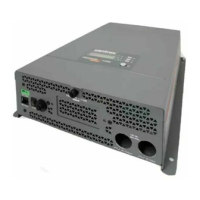
Basic Installation Procedures
975-0822-01-01 23
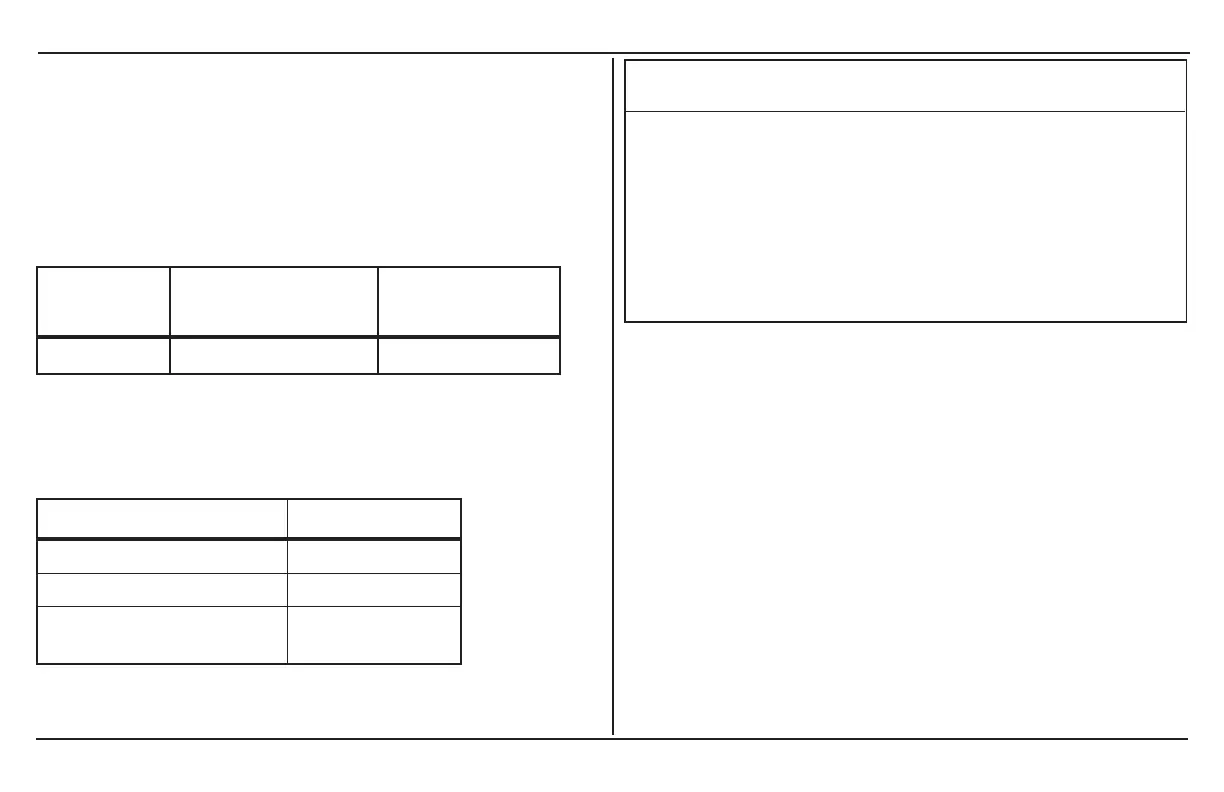
AC wiring must be sized appropriately using conductors with
insulation rated at least 75°C to carry full load current on the input
and output AC circuits in accordance with the electrical codes or
regulations applicable to your installation. Table 7shows a two-
conductor-plus-earth cable, using 75°C wiring, at an ambient
temperature of 30°C. Other codes and regulations may be
applicable to your installation.
Required Breaker
Size (A)
Required Wire
Size (mm
2
)
Freedom X 30 A maximum
6mm
2
Table 7Required AC wire size vs. required breaker rating
When making the AC input and AC output connections, observe the
correct color code for the appropriate AC wire, as described inTable
8 below.
Color AC Wire
Black/Red/Brown Line
White/light blue Neutral
Green, green/yellow, or bare
copper
Earth
Table 8Color codes for typical AC wiring
NOTICE
REVERSE POLARITY DAMAGE
Make sure the wires are connected properly. Improper connections
(connecting a line conductor to a neutral conductor, for example)
will cause the Freedom X to malfunction and may permanently
damage the inverter. Damage caused by a reverse polarity
connection is not covered by your warranty.
Failure to follow these instructions can result in equipment
damage.
Wiring Knockouts
When installing wires to the AC terminals, the AC input and output
holes are provided to accommodate PG16 (approximately 13mm)
strain relief clamps.
AC Input Connections
To make a permanent connection to existing AC wiring:
1. Ensure AC and DC power sources are turned off.
2. Install the required circuit breaker in the AC distribution
panel supplying AC power to the unit.
3. Remove the wiring compartment cover by loosening the
captive nut panel screw and lifting the cover up and out.
 Loading...