2-26
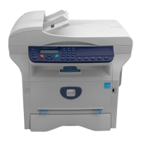
Phaser 3635MFP
08-500, 08-600
Draft 4
Status Indicator RAPs
08-500 Jam 2 RAP
08-500 The trail edge of the document failed to deactuate the exit sensor within the correct
time after registration.
Procedure
WARNING
Switch off the electricity to the machine. Disconnect the power cord from the customer
supply while performing tasks that do not need electricity. Electricity can cause death or
injury. Moving parts can cause injury.
WARNING
Do not touch the fuser while it is hot.
NOTE: The front cover assembly interlock switch must be closed to supply +24V to the motors
and clutches.
Refer to Wiring Diagram 2, Wiring Diagram 8 and Wiring Diagram 9. Perform the following:
1. Switch off the machine, then switch on the machine.
2. Open the rear door. Release the fuser pressure rolls, then remove all jammed paper.
3. Remove the fuser module, PL 10.10 Item 1. Check the paper path for damage or obstruc-
tions.
4. Open the fuser door, PL 10.12 Item 19. Check the following, install new components as
necessary:
a. The fuser exit sensor actuator, PL 10.12 Item 9 moves freely and is not damaged.
b. The fuser heat roll, PL 10.15 Item 1, pressure roll 1, PL 10.15 Item 2 and pressure
roll 2, PL 10.15 Item 3 are clean and rotate freely.
c. The fuser exit roll, PL 10.12 Item 6 and idlers, PL 10.12 Item 17 are clean and rotate
freely.
d. The fuser stripper fingers, PL 10.12 Item 13.
5. Remove the exit drive assembly, PL 10.20 Item 11. Check the following components are
clean and rotate freely:
a. Exit roll, PL 10.25 Item 22.
b. Exit roll idlers, PL 10.25 Item 3 and PL 10.25 Item 4.
c. Transport roll, PL 10.30 Item 6.
Install new components as necessary, PL 10.25 and PL 10.30.
6. Enter dC330 code 08-600. Check the fuser exit sensor (Q08-600). If necessary, install a
new HVPS, PL 1.10 Item 3.
NOTE: The fuser exit sensor is mounted on the HVPS.
7. Reinstall the fuser and the exit motor. Enter dC330 code 04-200. Check that the exit
motor (MOT04-200), PL 10.20 Item 4, runs and drives the fuser rolls, PL 10.15, and exit
roll, PL 10.12 Item 6.
8. Check the wiring between the exit motor and CN2 on the Connection PWB. Install new
components as necessary, PL 10.20 Item 4 and PL 3.10 Item 17.
9. Install new components as necessary:
• Duplex guide, PL 10.22.
• Connection PWB, PL 3.10 Item 17.
08-600 Duplex Jam 0 RAP
08-600 The lead edge of the document failed to actuate the duplex jam 1 sensor within the cor-
rect time.
Procedure
WARNING
Switch off the electricity to the machine. Disconnect the power cord from the customer
supply while performing tasks that do not need electricity. Electricity can cause death or
injury. Moving parts can cause injury.
NOTE: The front cover assembly interlock switch must be closed to supply +24V to the motors
and clutches.
Refer to Wiring Diagram 2 and Wiring Diagram 9. Perform the following:
1. Open the rear cover assembly, PL 8.20. Remove the duplex assembly, PL 10.23, then
remove all jammed paper.
2. Check the paper path for damage or obstructions.
3. Check that the duplex gate, PL 8.20 Item 9, moves freely and is not damaged.
4. Check that the duplex jam 1 sensor actuator, PL 8.25 Item 13 moves freely and is not
damaged. If necessary, install a new duplex jam 1 sensor actuator, PL 8.25 Item 13.
5. Enter dC330 code 08-700. Check the duplex jam 1 sensor (Q08-700). If necessary, install
a new HVPS, PL 1.10 Item 3.
NOTE: The duplex jam 1 sensor is mounted on the HVPS.
6. Remove the exit motor, PL 10.20 Item 4. Check the following components are clean and
rotate freely:
a. Exit roll, PL 10.25 Item 22.
b. Exit roll idlers, PL 10.25 Item 3 and PL 10.25 Item 4.
c. Transport roll, PL 10.30 Item 6.
d. Transport roll idlers, PL 10.25 Item 15.
Install new components as necessary, PL 10.25 and PL 10.30.
7. Reinstall the exit motor. Enter dC330 code 04-220 to run the exit motor in reverse. Check
that the exit motor runs and drives the exit rolls, PL 10.20 Item 4.
8. Check the wiring between the exit motor and CN2 on the Connection PWB. Install new
components as necessary, PL 10.20 Item 4, PL 3.10 Item 17.
9. Enter dC330 code 04-300 to run the duplex motor (MOT04-300), PL 10.20 Item 1. Check
that the duplex drive gear, PL 10.20 Item 12 rotates.
10. Check the wiring between the duplex motor and CN7 on the Connection PWB. Install new
components as necessary, PL 10.20 Item 1, PL 3.10 Item 17.
11. Manually rotate the duplex drive belt, PL 10.23 Item 12. Check that the duplex drive rolls,
PL 10.23 Item 13, PL 10.23 Item 14 are clean and rotate freely. Install new components
as necessary, PL 10.23.
12. Install new components as necessary:
• Duplex assembly, PL 10.23 Item 18.
• Connection PWB, PL 3.10 Item 17.

 Loading...


