Cable Hardware
Hardware User Guide 1-7
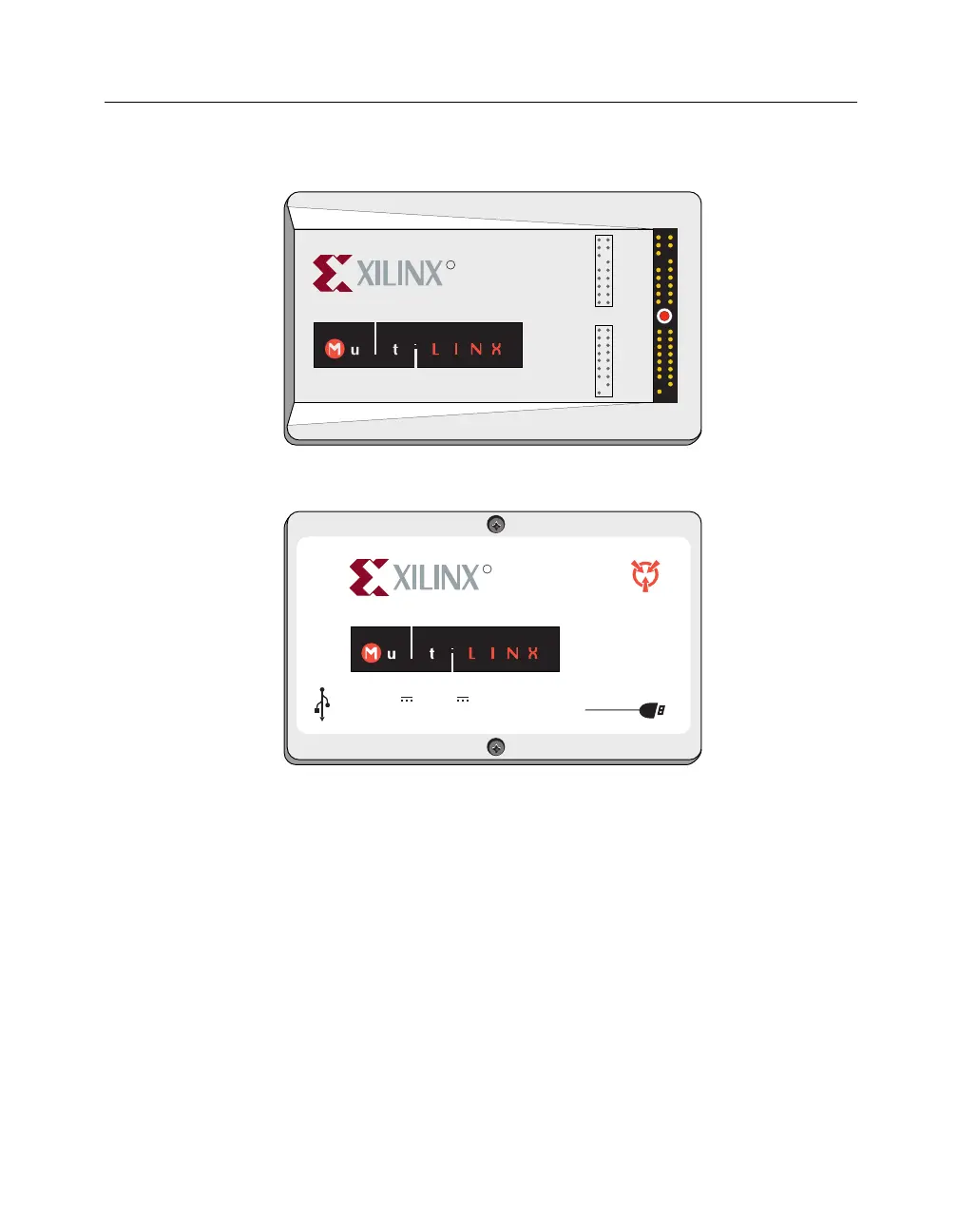
Figure 1-2 MultiLINX Cable
External Power for the MultiLINX Cable
The MultiLINX Cable gets its power from the User’s circuit board an
extended power supply. The cable power does not come from the
USB port (nor the RS-232 port). The red (PWR) and black (GND)
wires from Flying Wire Set #1 are connected to the VCC (red wire)
and Ground (black wire) lines of the circuit board that is powering
the Xilinx device. The external power for the MultiLINX Cable is
showninthefollowingfigure.
R
TM
USB
UNIVERSAL SERIAL BUS
Model: DLC6
Power: 2.5V 0.8A to 5V 0.4A Typ.
Serial: UC-
000074
Made in U.S.A
RS-232
CAUTION
SENSITIVE
ELECTRONIC
DEVICE
C E
R
RT
RT(TDO)
TRIG
TDI
TCK
TMS
CLK1-IN
CLK2-OUT
2 1
4 3
PWR
GND
CCLK
DONE
DIN
PROG
INIT
RST
D0
D1
D3
D4
D5
D6
D7
D2
CS0(CS)
CS1
CS2
CLK2-OUT
WS
RS(RDWR)
RDY/BUSY
CLK2-IN
TM
STATUS
Top View
Bottom View
X8927