Hardware User Guide
3-10 Xilinx Development System
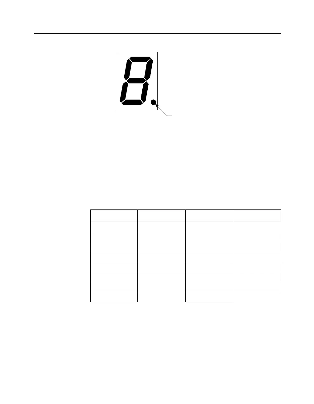
Figure 3-5 Seven-Segment Display
LED Indicators (D1-D8, D9-D16)
Eight LEDs are connected to the I/O pins of each FPGA. Pins D1
through D8 connect to the XC3020A, and D9 through D16 connect to
the XC4003E. You can turn on an LED by driving its corresponding
FPGA pin Low with a logic "0." The following table shows the pin
connections for the LED indicators.
Table 3-4 LED Indicators for XC3020A and XC4003E
LED XC3020A Pin LED XC4003E Pin
D1 37 D9 61
D2 36 D10 62
D3 41 D11 65
D4 33 D12 66
D5 32 D13 57
D6 31 D14 58
D7 28 D15 59
D8 29 D16 60
X4709
a
g
e
c
d
bf
Decimal point