Hardware User Guide
2-12 Xilinx Development System
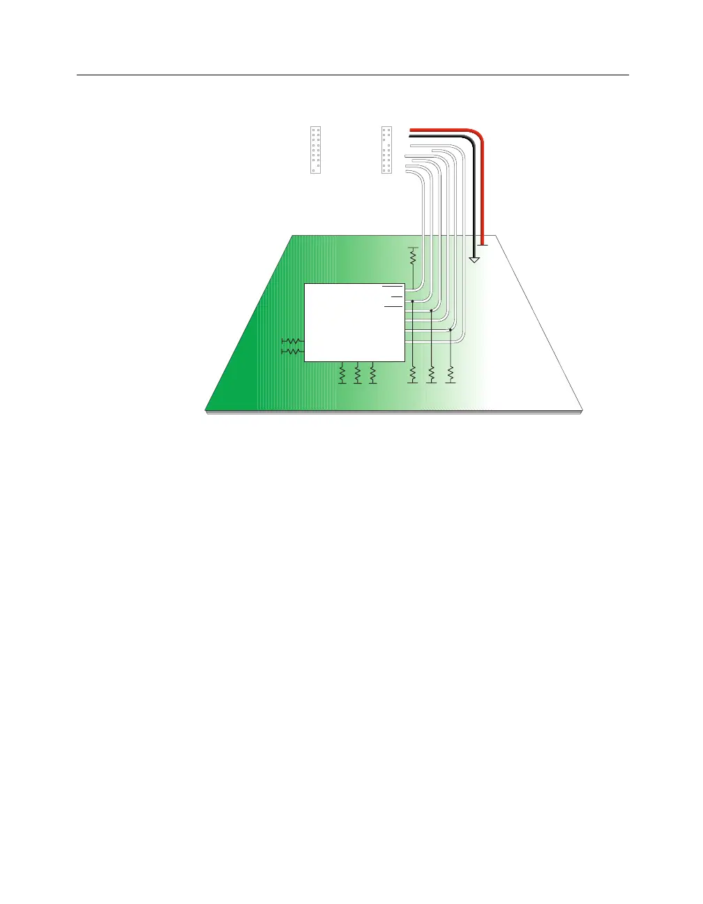
Figure 2-4 Slave Serial Mode (Virtex, Spartan, XC5200, XC4000)
Downloading Configuration Data or Verification of
Data
This section details the connections needed for downloading configu-
ration data or the verification of data with the MultiLINX Cable.
SelectMAP Mode (Virtex)
ThefollowingfigureshowsindetailtheSelectMAPModeconnec-
tions for Virtex devices.
D0
D1
D2
D3
D4
D5
D6
D7
RDY/BUSY
CS2
CS1
CS0 (CS)
WS
GND
CCLK
DIN
RT
TDI
TCK
TMS
RST
TRIG
RD (TDO)
PWR
VCC
VCC
RS (RDWR)
CLK2-IN
CLK2-OUT
CLK1-IN
CLK1-OUT
DONE (D / P)
PROG
INIT
4
2
3
1
NOTE: Pull-up resistors are 4.7k ohm.
VCC
Circuit Board
XILINX device
MultiLINX Connectors
VCCVCCVCC
(optional)
M0
M1
M2
INIT
CCLK
User I/O: RESET
TMS
DIN
DONE
PROG
VCC
TCK
VCC VCC VCC
X8941