MutliLINX
™
Cable
Hardware User Guide 2-19
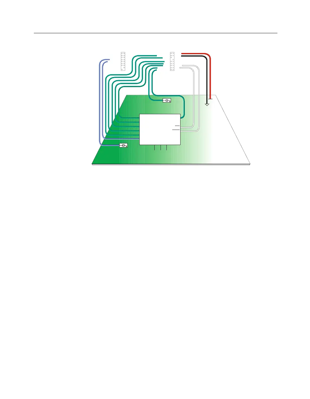
Figure 2-11 JTAG Mode (XC9000, Virtex, Spartan, XC5200,
XC4000
Verification of Configuration Data Only
This section details the connections needed for verification of config-
uration data only using the MultiLINX Cable.
Verification of Configuration Data Only (Spartan,
XC5200, XC4000)
The following figure shows in detail the connections for verification
of configuration data only with Spartan, XC5200, and XC4000
devices.
D0
D1
D2
D3
D4
D5
D6
D7
RDY/BUSY
CS2
CS1
CS0 (CS)
WS
GND
CCLK
DIN
RT
TDI
TCK
TMS
RST
TRIG
RD (TDO)
PWR
VCC
RS (RDWR)
CLK2-IN
CLK2-OUT
CLK1-IN
CLK1-OUT
DONE (D / P)
PROG
INIT
4
2
3
1
NOTE: Pull-up resistors are 4.7k ohm.
Circuit Board
XILINX device
MultiLINX Connectors
see data sheet of the device (if applicable)
(only XC4000 and SPARTAN)
(only XC4000 and SPARTAN)
System Clock (x)
System Clock (y)
(optional)
M0
M1
M2
INIT
TMS
PROG
TCK
TDI
TDO
GCK (x)
GCK (y)
User I/O: TRIGGER
(optional)
X8934