CPLD Design Demonstration Board
Hardware User Guide 4-5
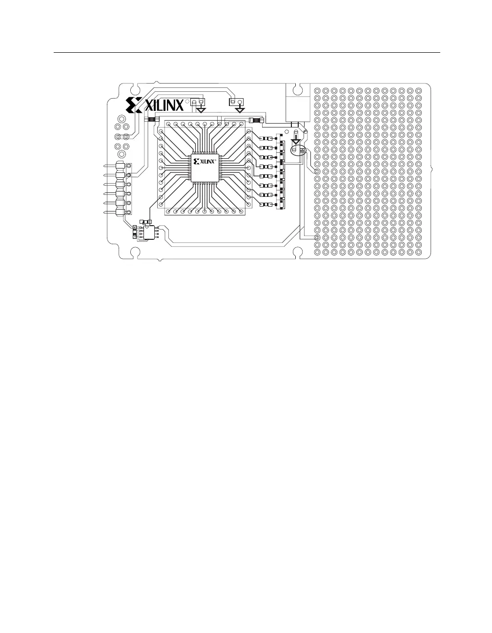
Figure 4-2 CPLD ISP Demonstration Board
All pins of the XC9536 device are connected to through-hole pads on
the PCB, numbered 1 to 44. Header Rows of 0.025 inch square posts
(on 0.10 inch centers) can be installed at these locations to provide
connection points for application circuitry.
Foundation Design Tutorial
The Xilinx Foundation Software Series contains the CPLD Jcounter
tutorial, which includes the following five design entry methods.
• JCT_SCH (schematic only)
• JCT_ABL (ABEL only)
• JCT_SABL (schematic with ABEL macro)
• JCT_VHD (VHDL only)
• JCT_SVHD (schematic with VHDL macro)
Example I: Schematic Design Entry
Example 1 shows the readme.txt file that is located in the project
directories of the Jcounter tutorial designs in the Xilinx Foundation
R
R
ISP DEMO BOARD
12 11109876543
22
21
20
19
18
17
16
15
14
13
12
34
35
36
37
38
39
40
41
42
43
44
3332 232425262728293031
J3
U2
C2
J2
+5V +9V
SW1
OFF
ON
J1
VCC
TMS
TDI
TDO
TCK
GND
C3
U3
R9
R8
D8
IN OUT
C4
GND
+5V
R1
D1
GND
+5V
C1
X8163
XC9536
U1