Hardware User Guide
1-18 Xilinx Development System
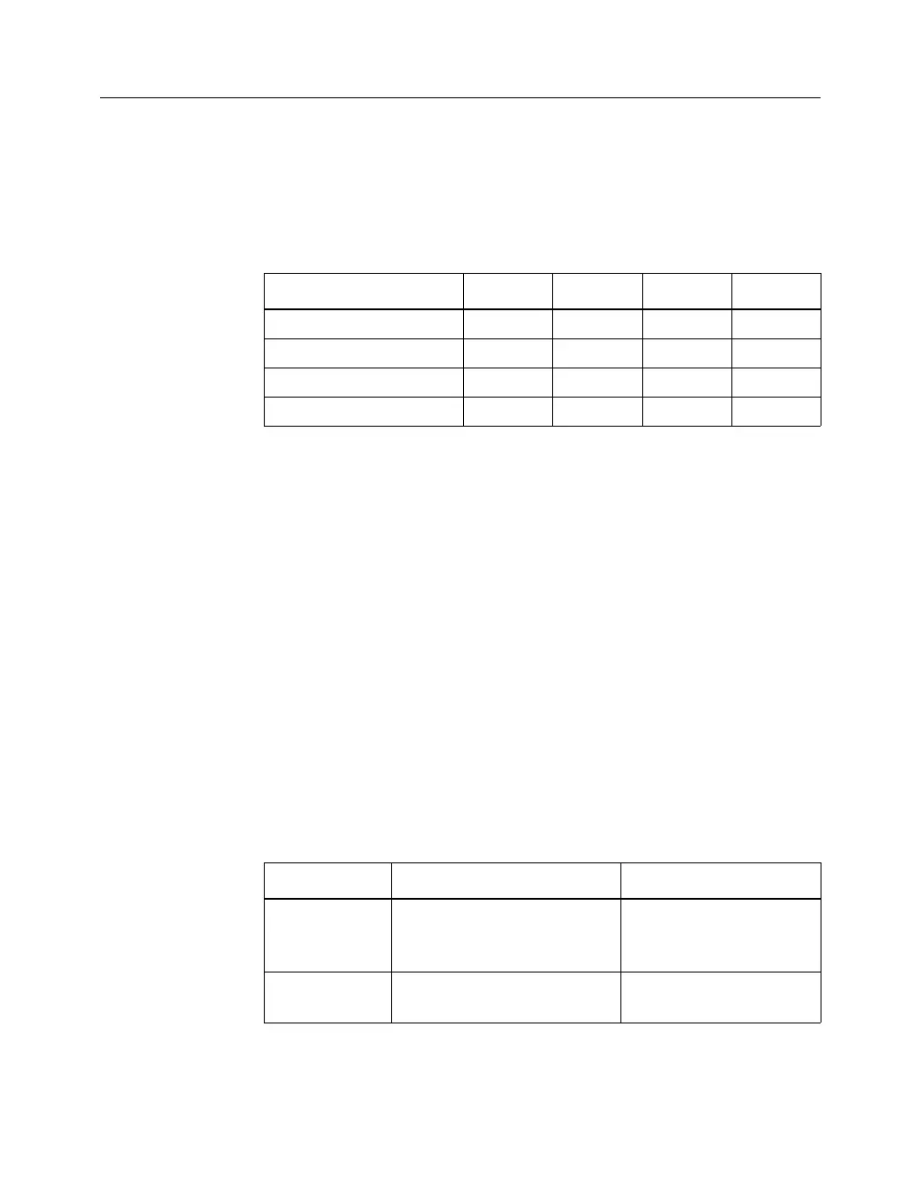
XChecker Baud Rates
Communication between your host system and the XChecker Cable
is dependent on host system capability. The XChecker Cable supports
several Baud rates and platforms, as shown in the following table.
Configuring CPLDs With the XChecker Cable
The JTAG Programmer should be used to program in JTAG mode.
When you configure a CPLD with the XChecker Cable, connections
between the cable assembly and the target system use only six of the
sixteen leads. For connection to JTAG boundary-scan systems you
need only ensure that the VCC, GND, TDI, TCK, TMS and RD (TDO)
pins are connected.
Note TRST is an optional pin in the JTAG (IEEE 1149.1) specification,
and is not used by XC9500 CPLDs (If any of your non-Xilinx parts
have a TRST pin, the pin should be connected to VCC).
Once installed properly, the connectors provide power to the cable
and allow download and readback of configuration data. The
following table describes the CPLD pin connections to the target
circuit board.
Table 1-4 Valid Baud Rates
Platform 9600 19200 38400 115.2K
IBM®PC XXXX
NEC PC X
SUN® XXX
HP700 XXXX
X indicates applicable baud rate
Table 1-5 XChecker Cable Pin Connections for CPLDs
Name Function Connections
VCC Power – Supplies VCC (5
V, 100 mA, typically) to the
cable
To target system VCC
GND Ground – Supplies ground
reference to the cable
To target system
ground