ZC702 Board User Guide www.xilinx.com 39
UG850 (v1.7) March 27, 2019
Feature Descriptions
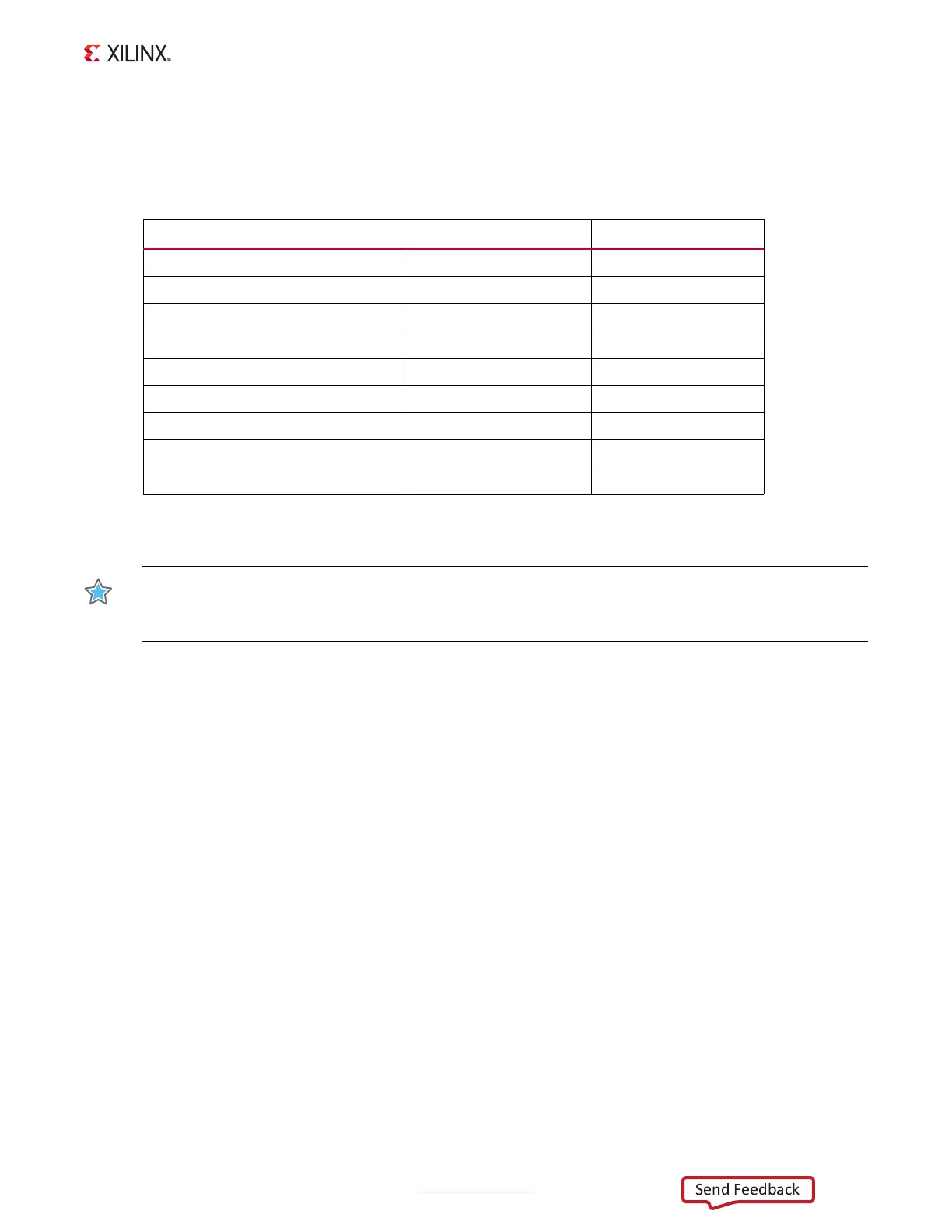
User applications that communicate with devices on one of the downstream I2C buses must
first set up a path to the desired bus through the U44 bus switch at I2C address 0x74
(0b11101 00). Table 1-19 lists the address for each bus.
IMPORTANT: The PCA9548 I2C bus switch U44 pin 24 net IIC_MUX_RESET_B is level-shifted by U81 and
is connected to the XCZ020 SoC U1 bank 500 pin A6. This is an active-Low signal and must be driven
High to enable I2C bus transactions between the U1 and the other components on the I2C bus.
Information about the PCA9548 is available on the TI Semiconductor website at [Ref 25].
Real-Time Clock
[Figure 1-2, callout 15]
The Epson RTC-8564JE is an 1
2
C bus interface real-time clock that has a built-in 32.768 KHz
oscillator with these features
• Frequency output options: 32.768 KHz, 1024 Hz, 32 Hz or 1 Hz
• Calendar output functions: Year, month, day, weekday, hour, minute and second
• Clock counter, alarm and fixed-cycle timer interrupt functions
Programming information for the RTC-8564JE is available in the RTC-8564JE/NB Application
Manual at the Epson Electronics America website [Ref 22].
Table 1-19: I2C Bus Addresses
I2C Device I2C Switch Position I2C Address
PCA9548 8-channel bus switch NA
0b1110100
Si570 clock 0
0b1011101
ADV7511 HDMI 1
0b0111001
I2C EEPROM 2
0b1010100
I2C port expander 3
0b0100001
I2C real time clock 4
0b1010001
FMC LPC J3 5
0bxxxxx00
FMC LPC J4 6
0bxxxxx00
UCD9248 controller PMBUS 7
0b01101[ADDR]
(1)
Notes:
1. This I2C address is the binary equivalent of the TI Power Controller PMBus decimal address 52, 53,
or 54 which corresponds to b00, b01 and b10 in the lower 2 bits.