ZC702 Board User Guide www.xilinx.com 51
UG850 (v1.7) March 27, 2019
Feature Descriptions
Switches
[Figure 1-2, callout 22–26]
The ZC702 board includes a power and a configuration switch:
• Power On/Off slide switch SW11 (callout 26)
• SW4 (FPGA_PROG_B), active-Low pushbutton (callout 22)
Power On/Off Slide Switch
[Figure 1-2, callout 20]
The ZC702 board power switch is SW11. Sliding the switch actuator from the Off to On
position applies 12V power from J60, a 6-pin mini-fit connector. Green LED DS14
illuminates when the ZC702 board power is on. See Power Management for details on the
onboard power system.
CAUTION! Do NOT plug a PC ATX power supply 6-pin connector into J60 on the ZC702 board. The ATX
6-pin connector has a different pinout than J60. Connecting an ATX 6-pin connector into J60 damages
the ZC702 board and voids the board warranty.
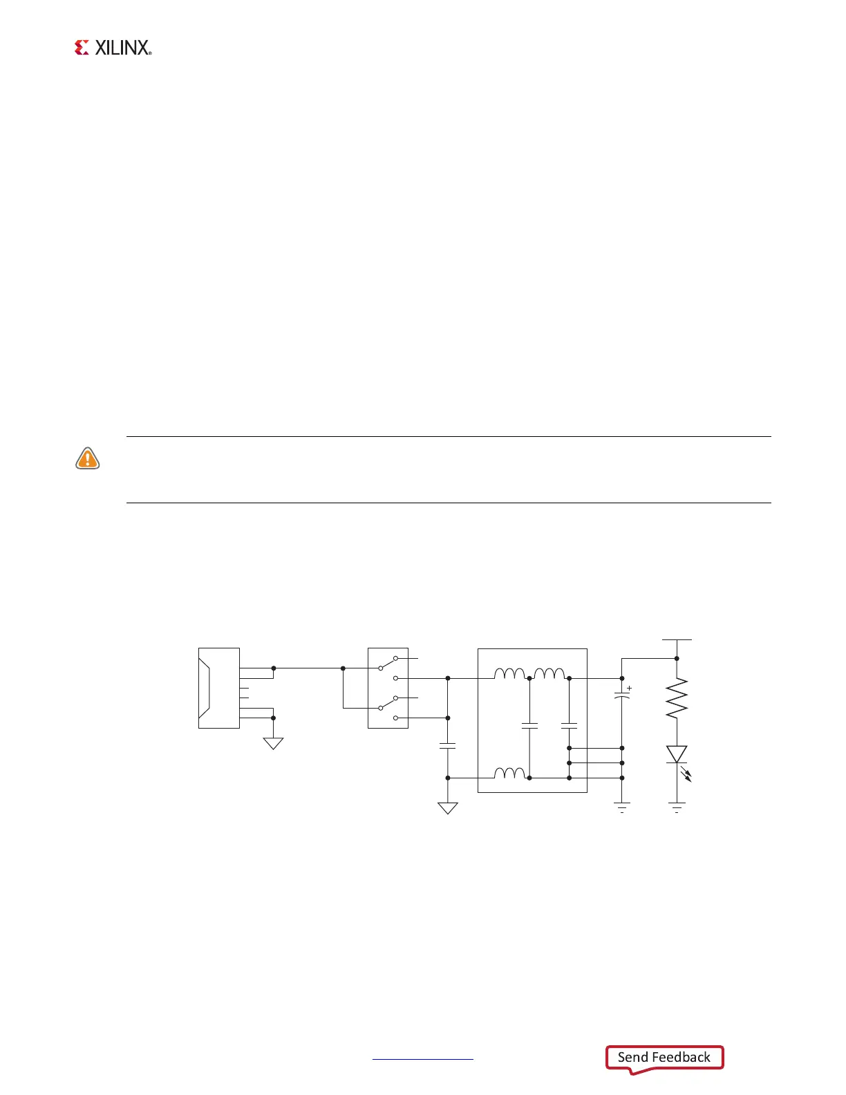
Figure 1-26 shows the power connector J60, power switch SW11 and indicator LED DS14.
X-Ref Target - Figure 1-26
Figure 1-26: Power On/Off Switch SW11
UG850_c1_26_030513
VCC12_P_IN
VCC12_P
R387
1kΩ
1%
INPUT_GND
1
2
3
4
SW11
GND
C517
330μF
25V
C512
1μF
25V
GND
DS14
5
6
J60
1
2
3
4
5
6
12V
N/C
COM
12V
N/C
COM
INPUT_GND
U78
1
3
8
7
6
5