ZC702 Board User Guide www.xilinx.com 47
UG850 (v1.7) March 27, 2019
Feature Descriptions
Table 1-23 lists the user LED connections to XC7Z020 SoC U1.
User Pushbuttons
[Figure 1-2, callout 18]
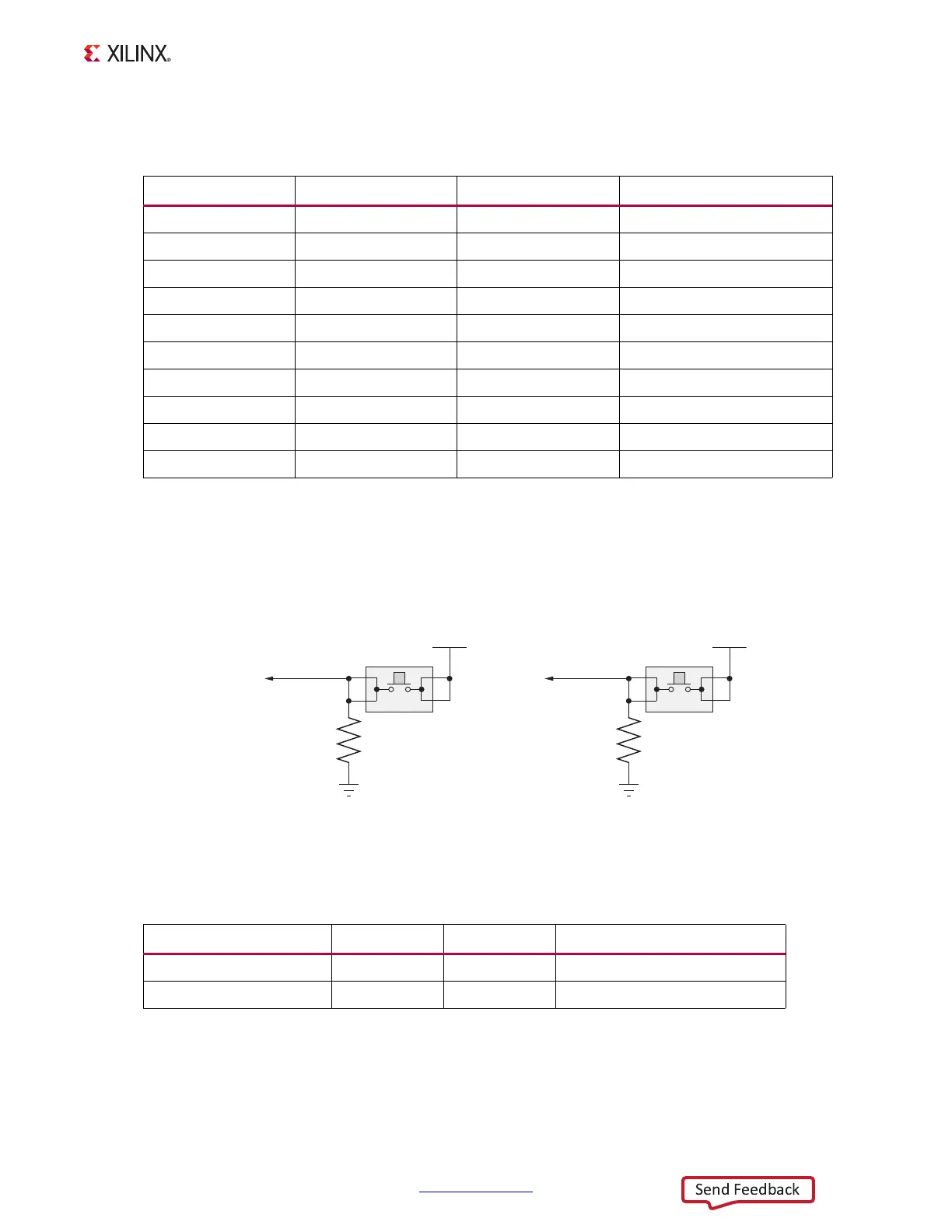
Figure 1-22 shows the user pushbutton circuits.
Table 1-24 lists the user pushbutton connections to XC7Z020 SoC U1.
Table 1-23: User LED Connections to XC7Z020 SoC U1
XC7Z020 (U1) Pin Net Name I/O Standard LED Reference Designator
E15 PMOD1_0 LVCMOS25 DS19
D15 PMOD1_1 LVCMOS25 DS20
W17 PMOD1_2 LVCMOS25 DS21
W5 PMOD1_3 LVCMOS25 DS22
V7 PMOD2_0 LVCMOS25 DS18
W10 PMOD2_1 LVCMOS25 DS17
P18 PMOD2_2 LVCMOS25 DS16
P17 PMOD2_3 LVCMOS25 DS15
Bank 501 G7 PS_LED1 N/A DS23
Bank 500 E5 PS_MIO8_LED0 N/A DS12
X-Ref Target - Figure 1-22
Figure 1-22: User Pushbuttons
Table 1-24: User Pushbutton Connections to XC7Z020 SoC U1
XC7Z020 SoC (U1) Pin Net Name I/O Standard Pushbutton and Pin Reference
G19 GPIO_SW_N LVCMOS25 SW5.3 (Left switch)
F19 GPIO_SW_S LVCMOS25 SW7.3 (Right switch)
VADJ
GPIO SW N
R352
4.7kΩ
0.1
Ω
5%
GND
4
32
1
SW5
VADJ
GPIO SW S
R354
4.7kΩ
0.1
Ω
5%
GND
4
32
1
SW7
UG850_c1_22_032719
Left Right