ZC702 Board User Guide www.xilinx.com 32
UG850 (v1.7) March 27, 2019
Feature Descriptions
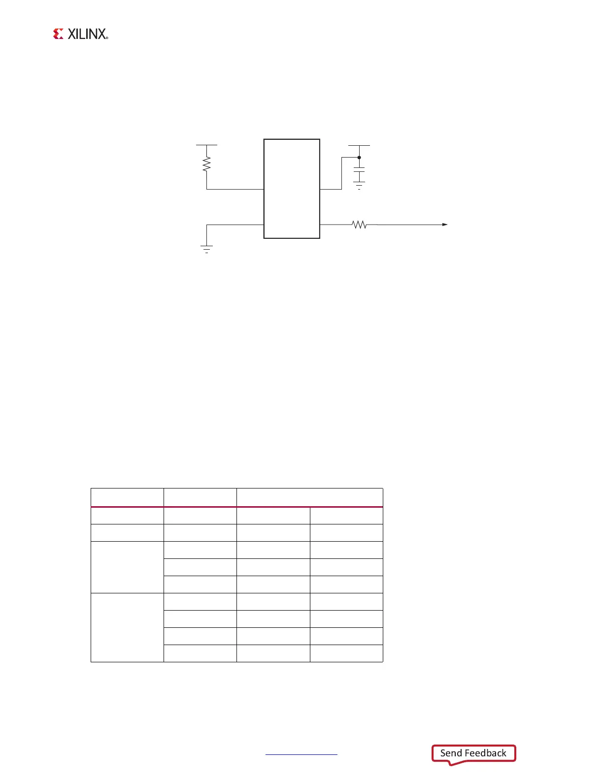
For more details, see the SiTime SiT8103 data sheet [Ref 18].
The system clock circuit is shown in Figure 1-13.
10/100/1000 MHz Tri-Speed Ethernet PHY
[Figure 1-2, callout 9]
The ZC702 board uses the Marvell Alaska PHY device (88E1116R) at U35 for Ethernet
communications at 10 Mb/s, 100 Mb/s, or 1000 Mb/s. The board supports RGMII mode
only. The PHY connection to a user-provided Ethernet cable is through a Halo HFJ11-1G01E
RJ-45 connector (P2) with built-in magnetics.
On power-up, or on reset, the PHY is configured to operate in RGMII mode with PHY
address
0b00111 using the settings shown in Table 1-13. These settings can be overwritten
using software commands passed over the MDIO interface.
X-Ref Target - Figure 1-13
Figure 1-13: Processing System Clock Source
Table 1-13: Board Connections for PHY Configuration Pins
U35 Pin Setting Configuration
CONFIG0 VCCO_MIO1 PHYAD[1]=1 PHYAD[0]=1
CONFIG1 EPHY_LED0 PHYAD[3]=0 PHYAD[2]=1
CONFIG2
GND ENA_XC=0 PHYAD[4]=0
EPHY_LED0 ENA_XC=0 PHYAD[4]=1
VCCO_MIO1 ENA_XC=1 PHYAD[4]=1
CONFIG3
GND RGMII_TX=0 RGMII_RX=0
EPHY_LED0 RGMII_TX=0 RGMII_RX=1
EPHY_LED1 RGMII_TX=1 RGMII_RX=0
VCCO_MIO1 RGMII_TX=1 RGMII_RX=1
UG850_c1_13_030513
GND
VCC1V8
SiT8103
MEMS Clock
Oscillator
33.33333 MHz
OE
GND
VDD
1
2
4
U65
R322
4.7KΩ 5%
C449
0.01 μF 25V
X7R
3
GND
VCC1V8
OUT
R403
24.9Ω 1%
PS CLK