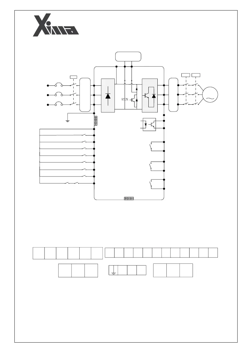
Fig. 6: General schematic of Xima
The Xima device has a row of 18 command terminals at the upper part and 9 power terminals
at the lower part. Wire the inverter, motor, and other related equipment as shown below. At
the top, power terminals are displayed separately from the control terminals. The external brake
resistance must also be connected to the B+ and B- terminals. 2 RJ45 terminals are provided for
encoder feedback.