M
B+
R
S
T
W
V
U
B-
PE
R
S
T
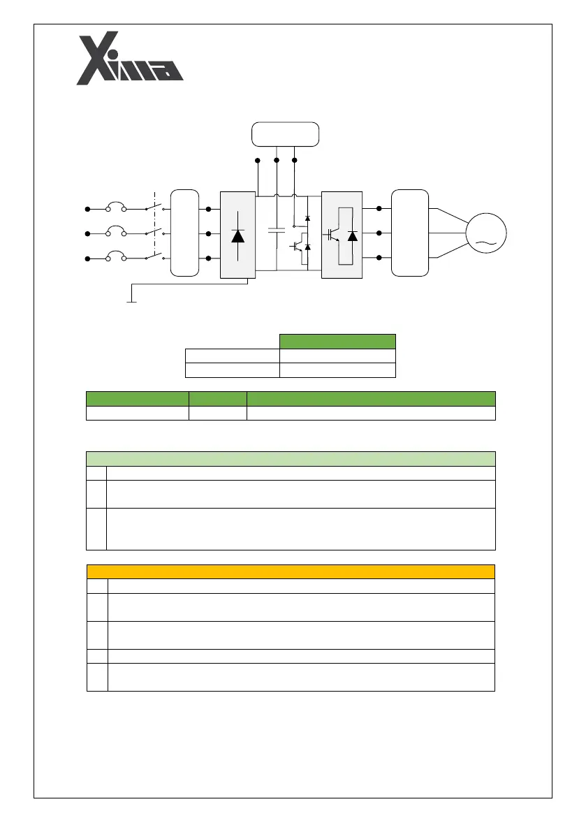
Input noise filter and
harmonic reduction
inductor
Output noise filter
Brake
resistance
P
Fig. 8: Illustration of input and output power terminals
Cross sections for input wire/output wire (mm
2
)
Table 6: Proper cross sections for input/output
Note that it is not necessary to connect the null to the N input.
Connect the ground wire to The PE terminal. In the three-phase model, use a wire
with a maximum cross-section of 1.5 mm
2
to connect the ground to the device.
Connect the brake resistance to the B+ and B- terminals with a 1.5 mm
2
cable (The
direction of the connection is not important). You can also use a thicker wire in the
single-phase model.
Avoid connecting the null directly to the ground.
Do not use any cable shoe. Using a cable shoe will increase the possibility of
loosening the terminal screws.
Strip to a maximum of 8 mm from the tip of the wires, such that the wires in the
adjacent terminals couldn't be connect to each other.
Never use a wire with a cross section larger than 4 mm
2
.
Avoid excessive tightening the terminal screws as the cost of replacing damaged
terminals is not covered by the warranty.