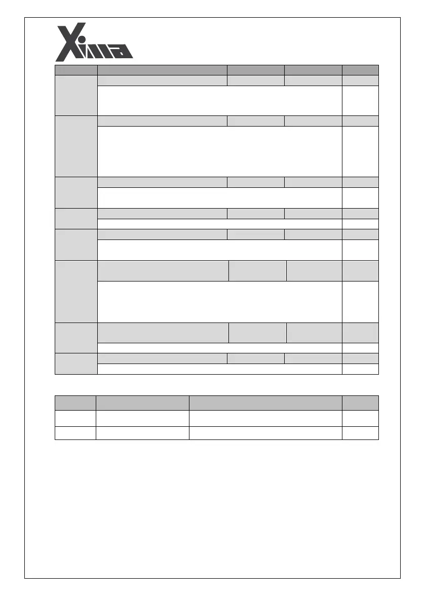
This parameter is used for enabling or disabling the small motor fault.
When the motor output current is less than the inverter's rated values,
the device shows this fault based on the inverter's internal parameters.
It specifies the number of times in which an inverter resets in the case of
a fault appearance. If it is set to 0, the inverter will require a manual reset
after any fault. Otherwise, when a fault happens, the inverter will be
reset for times. And when the counter of the faults becomes zero,
you will need to restart the inverter manually.
After a period of seconds, the fault occurred in the inverter (except
for the trip fault) will be reset.
After this time period, the trip fault will be reset.
If the motor speed exceeds % of the nominal motor speed, over
speed fault will occur.
Speed Diversion from Reference Fault
Level
Maximum allowed level for speed diversion from frequency reference.
If the output speed deviation from the reference is % more than
the rated motor speed for seconds, speed deviation fault will
occur.
Speed Diversion from Reference Fault
Time
Maximum allowed time for speed diversion from reference frequency.
Enabling or disabling the 12OC Fault
Displaying the inverter enabled inputs
Digital Output Monitoring
Displaying the inverter enabled outputs