EasyManuals Logo

Xylem hydrovar User Manual

Xylem hydrovar
116 pages
To Next Page IconTo Next Page
To Previous Page IconTo Previous Page
Page #106 background imageLoading...
Page #106 background image
Graph
Position numbers
2
H
Q
1
f = 100 %
1. The pressure at zero demand (all valves closed).
2. The pressure plus lift amount to compensate the friction loss.
11.4 Example: P500 SUBMENU SEQUENCE CNTR.
Graph
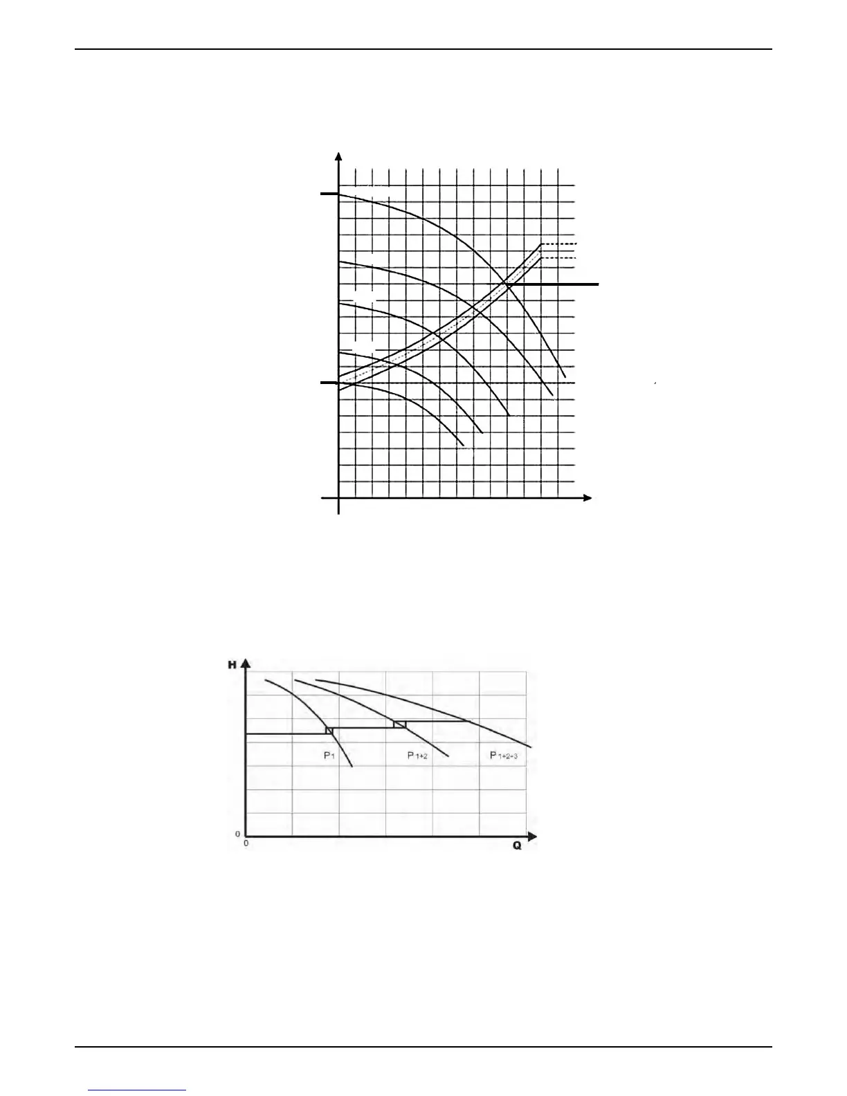
Calculation process for the sequence centre value
1. Lead pump reaches its P515 ENABLE FRQ.
2. Actual value falls to the cut in-value of the 1
st
assist pump. The 1
st
assist pump switches
on automatically. (Cut in-value = P02 REQUIRED VAL - P510 ACT.VAL.DEC)
3. A new required value, P03 EFF.REQ.VAL is calculated after the start up. P03
EFF.REQ.VAL = P02 REQUIRED VAL - P510 ACT.VAL.DEC + P505 ACT.VAL.INC
Calculations of the new required value for multi pump applications
k.... number of active pumps (k > 1)
11 Technical Reference
104 HVL 2.015-4.220 Installation, Operation, and Maintenance Manual

Table of Contents

Other manuals for Xylem hydrovar

Questions and Answers:

Question and Answer IconNeed help?

Do you have a question about the Xylem hydrovar and is the answer not in the manual?

Xylem hydrovar Specifications

General IconGeneral
Frequency50/60 Hz
Control typeVariable speed drive
Protection classIP55
Communication protocolsModbus
Relative Humidity5% - 95% (non-condensing)
AltitudeUp to 1000 m without derating
Input voltage200-690 V AC
Storage Temperature-25°C to +70°C (-13°F to 158°F)

Related product manuals