6.6.4 RS485 connection
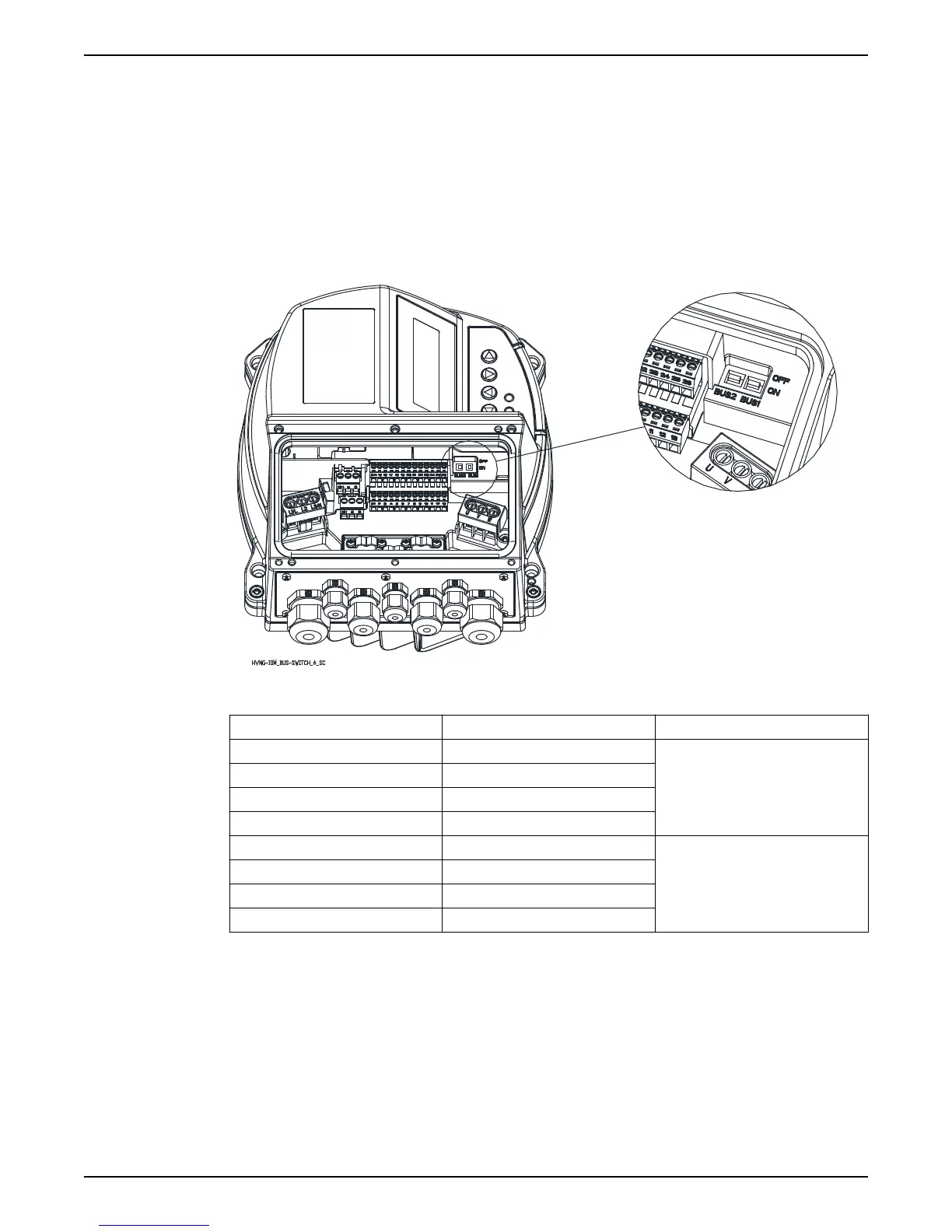
Terminals X1/11, X1/12 and X1/13 are used for the communication among up to 8
Hydrovar in a multi-pump application; a dedicated termination resistor switch (BUS1, see
image below) is made available to add a parallel terminator resistor to this RS485 port: if
the resistor is needed put BUS1 switch on ON position.
Terminals X1/24, X1/25 and X1/26 are used for the communication (via Modbus or Bacnet
protocol) with an external-control-device (e.g. PLC, BMS or a PC too); a dedicated
termination resistor switch (BUS2, see image below) is made available to add a parallel
terminator resistor to this RS485 port: if the resistor is needed put BUS2 switch on ON
position.
Table 9: RS485 ports
Terminals Description Comments
X1/11 RS485 port 1: RS485-1N
RS485 port 1 for multi-pump systems
X1/12 RS485 port 1: RS485-1P
X1/13 GND, electronic ground
BUS1 Termination resistor for port 1
X1/24 RS485 port 2: RS485-2N
RS485 port 2 for external
communication
X1/25 RS485 port 2: RS485-2P
X1/26 GND, electronic ground
BUS2 Termination resistor for port 2
6.6.5 Status relays
Terminals X2/4, X2/5 and X2/6 are used to make available Status Relay 1 contacts, for
driving an external relay used as pump status configurable indicator.
Terminals X2/1, X2/2 and X2/3 are used to make available Status Relay 2 contacts, for
driving an external relay used as pump status configurable indicator.
6 Electrical Installation
HVL 2.015-4.220 Installation, Operation, and Maintenance Manual 37